Spiral pump for pneumatic transmission

A pneumatic conveying and screw pump technology, applied in the field of screw pumps, can solve problems such as difficult control of feeding volume, sticking, and blocked pipes

Inactive Publication Date: 2010-06-09
ZHUZHOU SMELTER GRP +1
View PDF0 Cites 2 Cited by
  • Summary
  • Abstract
  • Description
  • Claims
  • Application Information

AI Technical Summary

Problems solved by technology

When feeding with the warehouse pump pneumatic conveying device, it is often difficult to convey or the material blocks the pipeline, mainly because the feeding amount is not easy to control and the output is uneven; in addition, due to the high concentration of the conveyed materia...

Method used


Image

  • Spiral pump for pneumatic transmission
  • Spiral pump for pneumatic transmission
  • Spiral pump for pneumatic transmission

Examples


Embodiment Construction

[0019] The following will clearly and completely describe the technical solutions in the embodiments of the present invention with reference to the accompanying drawings in the embodiments of the present invention. Obviously, the described embodiments are only some, not all, embodiments of the present invention. Based on the embodiments of the present invention, all other embodiments obtained by persons of ordinary skill in the art without creative efforts fall within the protection scope of the present invention.

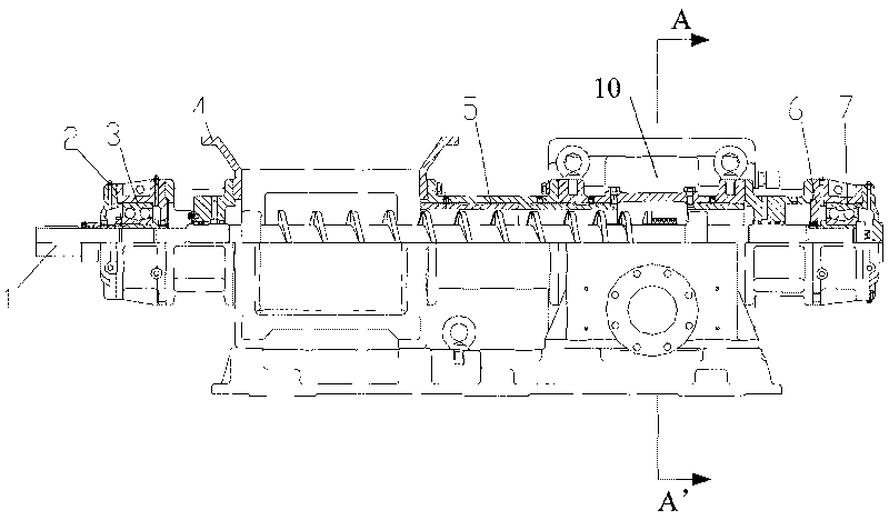
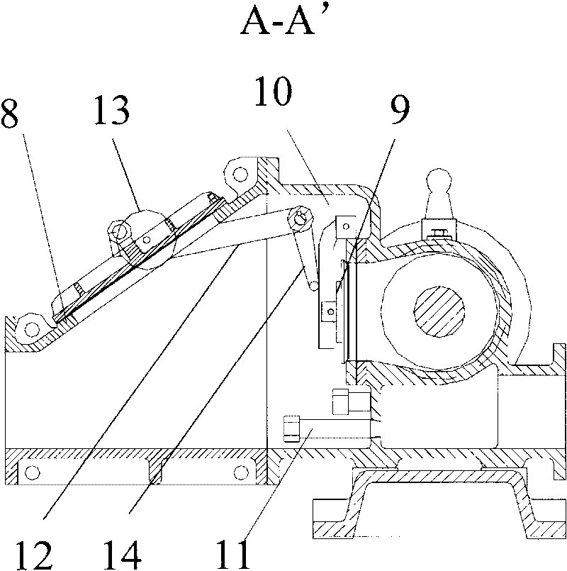
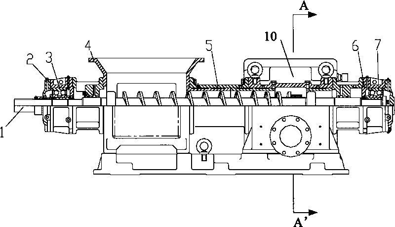
[0020] See figure 1 with figure 2 , a screw pump for pneumatic conveying, comprising: a screw shaft 1, a feed box 4, a mixing box 10, a nozzle 11, a wear-resistant sleeve 5 and a discharge box 8; wherein, the feed box 4, the wear-resistant sleeve 5 , The mixing box 10 and the unloading box 8 are sequentially connected, the screw shaft 1 is arranged in the space formed by the feed box 4 and the wear-resistant sleeve 5, and the screw shaft 1 can rotate around its o...


PUM


Abstract

The invention discloses a spiral pump for pneumatic transmission, which comprises a feeding box, a spiral shaft, a wear-resistant sleeve, a nozzle, a mixing box and a discharging box. The feeding box, the wear-resistant sleeve, the mixing box and the discharging box are communicated in order. The spiral shaft penetrates a space formed by the feeding box and the wear-resistant sleeve in order, and two ends of the spiral shaft can rotate around the self-axis through a bearing; and the mixing box is connected with the nozzle. After entering the feeding box, powdery materials pass through the wear-resistant sleeve from the feeding box along a screw of the spiral shaft, finally the powdery materials are brought into the mixing box. After the materials are discharged into the mixing box, compressed air is injected into the mixing box through the nozzle, so that the materials are fully fluidized, and then the fluidized materials are conveyed to a conveying pipeline which is connected with the end part of the mixing box. In the whole conveying process, the spiral shaft can uniformly convey the materials from the feeding box to the mixing box, so that the materials in the mixing box can be fully fluidized, and finally the materials smoothly pass through the conveying pipeline.

Description

technical field [0001] The invention relates to a screw pump for pneumatic conveying of zinc oxide. Background technique [0002] Pneumatic conveying, also known as airflow conveying, mainly uses the energy of airflow to transport granular materials along the direction of airflow in a closed pipeline, which is a specific application of fluidization technology. The pneumatic conveying device has a simple structure and is easy to operate. It can be used for horizontal, vertical or inclined conveying. During the conveying process, it can also perform physical operations such as heating, cooling, drying and air classification of materials or certain chemical operations. [0003] In the prior art, the warehouse pump pneumatic conveying device first fills the material into the pressure vessel, and then fills the airtight pressure vessel with compressed air, so that the air and the material are pressed into the pipeline together for transportation. When feeding with the warehouse ...

Claims


Application Information

Patent Timeline
IPC IPC(8): F04D3/02
Inventor 肖功明叶柏瑞巫之俊谢斌李步渠陈振东肖永高肖康彭志亮谢永军徐迅
Owner ZHUZHOU SMELTER GRP
Why Eureka
Try Eureka