Pressure container and gas inlet thereof

A pressure vessel and air inlet technology, which is applied in the field of pressure vessels and their air inlets, can solve the problems of insufficient improvement of the flow state factor entering the shell, difficulty in setting the material inlet and outlet 5, and failure to fundamentally solve the problem, etc. The layout is safe and scientific, the particle size and ingredient quality are uniform, and the operation is flexible.

Inactive Publication Date: 2016-11-09
THE CHALLENGE PETROCHEM MACHINERY CORP
View PDF6 Cites 1 Cited by
  • Summary
  • Abstract
  • Description
  • Claims
  • Application Information

AI Technical Summary

Problems solved by technology

In the prior art, the gas-solid fluidized bed distribution plate has more or less defects such as weak anti-sedimentation ability, low stability, easy to be blocked by active substances, etc., and the original distribution plate structure also exists in the reactor shell structure. Issues such as functional adaptability after upsizing
In this regard, people have made great efforts to improve the distribution plate structure of the gas-solid fluidized bed inside the reactor. On the main body, structures such as a circular plate shape, a truncated cone shape, and a funnel-shaped inverted cone have been developed, and new structures such as a concave-convex combination shape have also been proposed. In terms of details, various designs and practices have been carried out on the air distribution holes on the distribution plate. Although the overall effect has been improved, the problem has not been fundamentally solved.
[0004] In fact, the above-mentioned instability problem of gas fluidized bed can be further divided into two categories: primary instability and secondary instability. The previous technology is too focused on the latter secondary instability. That is, the distribution plate, but the improvement of the former primary instability, that is, the flow state factor of the process gas entering the shell, is not enough. At the same time, the technical research on the relationship between primary instability and secondary instability and their structural matching is close to blank
figure 2 Yes figure 1 The D-D direction view in the figure analyzes the function of its non-radial process gas inlet structure 8. Since there is only one process gas inlet, the process gas entering the spherical lower head 3 is usually unevenly distributed. If the only process gas inlet is changed to It is the middle inlet at the bottom of the head, although it can obviously improve the uniformity of process gas distribution, but it also makes it difficult to set up the material inlet and outlet 5
With the increase of the diameter of the container and the production scale, the flow rate of the reaction process is large, and the contradiction of this single inlet is intensified, which is manifested in the fast gas flow that easily causes vibration, and also increases the new problem of poor operating flexibility.

Method used


Image

  • Pressure container and gas inlet thereof
  • Pressure container and gas inlet thereof
  • Pressure container and gas inlet thereof

Examples


Embodiment 1

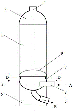
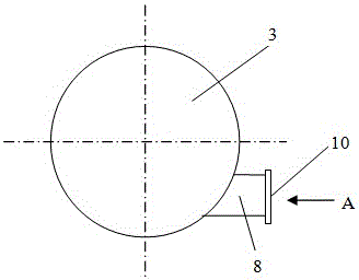
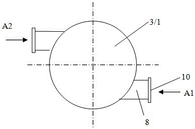
[0050] A pressure vessel and its air inlet of the present invention, the air inlet is located on the cylinder or head below the lower distribution plate in the vertical pressure vessel shell, specifically, refer to image 3 The truncation to the dual inlet takes over, with the figure 2 Compared with the traditional single inlet nozzle, there is only one more inlet nozzle, and its manufacturing process remains unchanged, but the diameter of the nozzle can be reduced under the same process air flow rate, which should be determined through design calculations.

[0051] The tangential direction refers to the intersection of the busbar on the long side and the arc of the head 3 or the cylinder 1 to form a bow.

Embodiment 2

[0053] The second specific embodiment of a pressure vessel and its axisymmetric air inlet of the present invention, refer to Figure 4 As shown, the main technical solutions of this embodiment are the same as those of Embodiment 1, and the features not explained in this embodiment are explained in Embodiment 1, and will not be repeated here. The difference between this embodiment and Embodiment 1 is that the number of the non-radial and tangential intake pipes increases from two evenly distributed to three.

Embodiment 3

[0055] The third specific embodiment of a pressure vessel and its axisymmetric air inlet of the present invention, refer to Figure 5 As shown, the main technical solutions of this embodiment are the same as those of Embodiment 1, and the features not explained in this embodiment are explained in Embodiment 1, and will not be repeated here. The difference between this embodiment and Embodiment 1 is that the tangential inlet connection is a connection structure with two-sided openings tangential to the shell, and the tangential direction refers to the circle between the long-side busbar and the head 3 or cylinder 1. The smooth transition of the arcs is tangent to each other, and no longer cuts out a bow.


PUM


Abstract

The invention provides a gas inlet of a pressure container. The gas inlet is located in a barrel or a shell cover below a distribution plate on the lower portion in a shell of the vertical pressure container, and circumferential openings are formed in the distribution plate. The gas inlet of the pressure container comprises at least two tangential penetration type oblique openings formed in axial symmetry along the shell. The pressure container is provided with at least two gas inlets formed in axial symmetry in shape and position, gas inflow connecting pipes are conveniently installed, the flow state of process gas entering the shell is improved, the flow speed is reduced, pressure is balanced, impact vibration is avoided, then the process gas flows out through the radial openings in the gas flow distribution plate, materials from the upper portion of a reactor to which the pressure container belongs form a balanced fluidized bed, and the capacity large scale is achieved. The invention further discloses the pressure container. Gas flow balance, particle product fluidity and internal structure fatigue resistance can be considered at the same time, the advantages of being high in anti-deposition capacity, stable in production and the like are achieved, the spatial arrangement is safer and more scientific, and the service life of the pressure container can be prolonged.

Description

technical field [0001] The present invention relates to the technical field of various large-scale high-grade reactors used in petroleum refining and chemical industry, coal chemical industry, chemical fertilizer industry and other various chemical equipment, for example, fluidized bed reactor, hydrogenation reaction through catalyst reaction device or desulfurization reactor, etc., especially relates to a pressure vessel and its air inlet. Background technique [0002] chemical reactors, such as figure 1 As shown, it includes a cylinder body 1, the heads arranged at both ends of the cylinder body are the upper head 2 and the spherical lower head 3, the material inlet and outlet of the head are the upper opening 4 and the lower opening 5, and the support 6, The support ring 7, the process gas inlet structure 8, the gas flow distribution plate 9 arranged in the cylinder, and the inner support structure used to support the gas flow distribution plate, or the support structure...

Claims


Application Information

Patent Timeline
Patent Type & Authority Applications(China)
IPC IPC(8): B01J3/02B01J3/04
CPCB01J3/02B01J3/04
Inventor 陈孙艺雷小娣
Owner THE CHALLENGE PETROCHEM MACHINERY CORP
Why Eureka
Try Eureka