Gate valve

A technology of valve seat and valve plate, which is applied in the field of plug-in valves, can solve the problems of short service life, poor sealing effect, and uneven sealing force on both sides of the valve, and achieve the advantages of prolonging service life, improving sealing reliability, and improving standardization Effect

Active Publication Date: 2010-06-09
JIANGSU SHENTONG VALVE
View PDF0 Cites 13 Cited by
  • Summary
  • Abstract
  • Description
  • Claims
  • Application Information

AI Technical Summary

Problems solved by technology

[0003] In order to overcome the disadvantages of uneven sealing force on both sides, poor sealing effect and short service life of the valve due to the movement of the valve plate in the existing gate valve, the present invention provides a gate valve

Method used


Image

  • Gate valve
  • Gate valve
  • Gate valve

Examples


Embodiment Construction

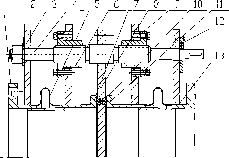
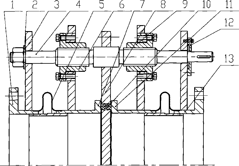
[0010] like figure 1 As shown, a flapper valve includes a left valve body 1, a bellows 5, a valve plate 8, a sealing ring 10, a screw rod 4, a left nut 6, a right nut 9, a right valve body 13, a left valve seat 7, a right The valve seat 11, the bellows 5 is welded between the left valve seat 7 and the left valve body 1, the sealing ring 10 is installed in the groove of the valve plate 8, the valve plate 8 is fixed in the middle of the screw rod 4, and the left end of the screw rod 4 passes through The left nut 6 is installed on the left valve seat 7, the right end of the screw rod 4 is installed on the right valve seat 11 through the right nut 9, and a bellows 5 is also welded between the right valve seat 11 and the right valve body 13; A support plate 3 is installed on the top, and the screw rod 4 passes through the support plate 3 and is fixedly connected with the left valve body 1 through the limit plate 2. The right valve body 13 is equipped with a support plate 3, and the...


PUM


Abstract

The invention provides a gate valve, which comprises a left valve body, corrugated pipes, a valve plate, seal rings, a screw rod, a left nut, a right nut, a right valve body, a left valve seat and a right valve seat. A corrugated pipe is welded between the left valve seat and the left valve body; seal rings are arranged in a groove of the valve plate; the valve plate is fixed on the middle part of the screw rod; the left end of the screw rod is arranged on the left valve seat through the left nut; the right end of the screw rod is arranged on the right valve seat through the right nut; another corrugated pipe is also welded between the right valve seat and the right valve body; a bearing plate is arranged on the left valve body; the screw rod passes through the bearing plate and then is fixedly connected with the left valve body through a limit plate; a bearing plate is arranged on the right valve body; and the screw rod passes through the bearing plate and then is fixedly connected with the right valve body through the limit plate and a gland. The gate valve has the advantages that: when the gate valve moves, the valve plate does not move; the sealing reliability is greatly improved because the seal rings on two sides of the valve plate is uniformly stressed; the service life of the product is prolonged; and production is conveniently organized and the management is convenient.

Description

technical field [0001] The invention relates to a valve, in particular to a plug valve. Background technique [0002] At present, the plug-in valve used in the gas system of the metallurgical industry adopts a bellows. When the screw rod rotates and moves horizontally during operation, the valve plate will also move horizontally under the action of the screw rod, causing the sealing rings on both sides of the valve plate to be affected. The uneven force will affect the sealing performance of the valve. At the same time, due to the movement of the screw, it will have an adverse effect on the connection between the swing arm that drives the screw to rotate and the drive device, and affect the service life of the product. Contents of the invention [0003] In order to overcome the disadvantages of uneven sealing force on both sides, poor sealing effect and short service life of the valve due to the movement of the valve plate in the existing flapper valve, the invention provi...

Claims


Application Information

Patent Timeline
Patent Type & Authority Applications(China)
IPC IPC(8): F16K3/16F16K27/04F16K3/30
Inventor 张逸芳
Owner JIANGSU SHENTONG VALVE
Why Eureka
Try Eureka