Low-temperature thermoacoustic refrigerator

A low-temperature heat and refrigerator technology, which is applied in the direction of refrigerators, refrigeration and liquefaction, compressors, etc., can solve the problems that refrigerators occupy small space, occupy large space, and the volume of refrigeration components 2 is large, so as to reduce volume and occupy space , the overall footprint is low, and it is easy to promote and apply

Inactive Publication Date: 2010-06-09
LIHAN CRYOGENICS
View PDF0 Cites 14 Cited by
  • Summary
  • Abstract
  • Description
  • Claims
  • Application Information

AI Technical Summary

Problems solved by technology

[0004] In practical applications, due to the long inertia tube 26 and the large volume of the gas storage 27, the volume of the entire refrigeration unit 2 is relatively large, and the occupied space is also large; at the same time, the oscillatory wave generating unit 1 and the refrigeration unit 2 are independent The configuration also leads to the large volume and occupied space of the entire low-temperature refrigerator. For some occasions, such as superconducting devices, infrared imaging, gasification and liquefaction, or high-vacuum acquisition, etc., the refrigerator requires a small footprint, and the existing low-temperature thermal The acoustic refrigerator has a large structure and cannot meet the actual needs, which limits the application of low-temperature thermoacoustic refrigerators
[0005] In the process of realizing the present invention, the inventors found that the prior art has at least the following problems: the existing low-temperature thermoacoustic refrigerators are not compact in structure, large in volume, large in space, and poor in practicability, which limits the use of low-temperature thermoacoustic refrigerators. promotion and application

Method used


Image

  • Low-temperature thermoacoustic refrigerator
  • Low-temperature thermoacoustic refrigerator
  • Low-temperature thermoacoustic refrigerator

Examples


Embodiment Construction

[0033] In order to make the purpose, technical solutions and advantages of the embodiments of the present invention clearer, the technical solutions in the embodiments of the present invention will be clearly and completely described below in conjunction with the drawings in the embodiments of the present invention. Obviously, the described embodiments It is a part of embodiments of the present invention, but not all embodiments. Based on the embodiments of the present invention, all other embodiments obtained by persons of ordinary skill in the art without creative efforts fall within the protection scope of the present invention.

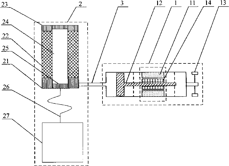
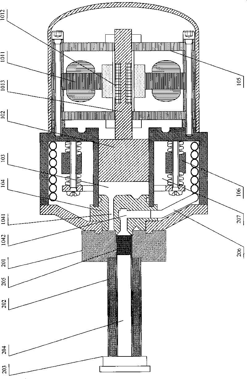
[0034] figure 2 It is a structural schematic diagram of Embodiment 1 of the low-temperature thermoacoustic refrigerator of the present invention. Such as figure 2 As shown, the low-temperature thermoacoustic refrigerator of this embodiment includes: an oscillating wave generating component and a cooling component. The oscillating wave generati...


PUM


Abstract

The invention discloses a low-temperature thermoacoustic refrigerator which comprises an oscillation wave generating part and a refrigerating part, wherein the oscillation wave generating part comprises a rotor, a stator, a piston, a passive oscillator and a cylinder; the refrigerating part comprises a first radiator, a heat regenerator, a cold finger, a heat buffer tube, a second radiator, an inertia tube and a gas reservoir which are sequentially communicated; the gas reservoir is surrounded outside the cylinder, and the inertia tube is wound on the inner wall of the gas reservoir; the end part of the cylinder is provided with a connecting piece connected with the first radiator and the second radiator, and a first gas hole and a second gas hole are arranged on the connecting piece; the first radiator is communicated with the cylinder through the first gas hole, and the second radiator is connected with the inertia tube through the second gas hole; when the oscillation wave generating part works, the piston reciprocates and generates oscillation waves under the drive of the rotor; and the oscillation waves enter the heat regenerator through the first gas hole and the first radiator. The embodiment has compact structure and small size and occupied area and improves the practicability of low-temperature thermoacoustic refrigerators.

Description

technical field [0001] The invention relates to the technical field of refrigerators, in particular to a low-temperature thermoacoustic refrigerator. Background technique [0002] A refrigerator is a device that transfers heat from a cooled object to another medium to cool the object to be cooled. Among them, a low-temperature thermoacoustic refrigerator is an important low-temperature refrigeration device. [0003] figure 1 It is a structural schematic diagram of a low-temperature thermoacoustic refrigerator in the prior art. Such as figure 1 As shown, the existing low-temperature thermoacoustic refrigerator includes: an oscillating wave generating part 1 and a cooling part 2 independently arranged, wherein the oscillating wave generating part 1 includes: a stator 11, a piston 12, a passive vibrator 13 and a mover 14; Part 2 mainly includes: a first radiator 21, a regenerator 22, a cold head 23, a thermal buffer pipe 24, a second radiator 25, an inertia tube 26 and an ai...

Claims


Application Information

Patent Timeline
Patent Type & Authority Applications(China)
IPC IPC(8): F25B9/00
Inventor 胡剑英罗二仓戴巍李海冰
Owner LIHAN CRYOGENICS
Why Eureka
Try Eureka