Electronic belt scale nutation type belt tensioning device

An electronic belt scale and tensioning device technology, applied in measuring devices, instruments, weighing and other directions, can solve the problems of excessive eccentric load, bulky equipment, and bulky mechanism, so as to achieve labor-saving tensioning and relaxation, and save space. , the effect of reducing manpower

Active Publication Date: 2010-06-09
云南昆船电子设备有限公司
View PDF0 Cites 4 Cited by
  • Summary
  • Abstract
  • Description
  • Claims
  • Application Information

AI Technical Summary

Problems solved by technology

[0002] Various electronic belt scales currently on the market use fixed tensioning, heavy hammer tensioning, or lever tensioning for belt tensioning methods, but no matter which tensioning method is used, it is very difficult. It is difficult to quickly tension or relax the belt, and the way of tensioning or relaxing the belt is complicated and difficult to operate; in order to make the tensioning mechanism produce enough tension on the belt, the tensioning device is often designed to be cumbersome, which is very difficult for the equipment. Difficulties in assembly and commissioning work, and heavy equipment is not conducive to transportation and placement
[0003] On the other hand, when the belt needs to be replaced due to aging, damage or other reasons, due to the complex way of tensioning and relaxing the belt and the cumbersome mechani...

Method used


Image

  • Electronic belt scale nutation type belt tensioning device
  • Electronic belt scale nutation type belt tensioning device
  • Electronic belt scale nutation type belt tensioning device

Examples


Embodiment Construction

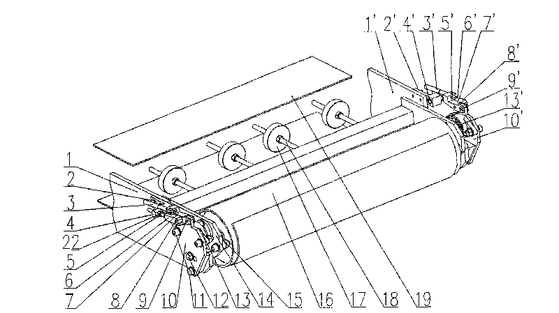
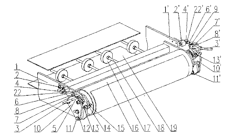
[0022] Such as figure 1 , figure 2 As shown, the present invention includes a tensioning frame 14 straddling the two ends of the driven roller 16 of the electronic belt scale and positioned between the upper and lower belts, the fuselage side panels 1, 1' symmetrically arranged on the two outer sides of the tensioning frame, and being installed on the machine. Linkages on the side panels. The connecting rod mechanism is composed of bases 2, 2', first connecting rods 6, 6', second connecting rods 7, 7', and deflection plates 10, 10' connected in sequence. The bases 2, 2' are fixed on the side panels of the fuselage. The first connecting rod 6,6' is hinged with the base 2,2' through the first rotating shaft 4,4', and the connecting section between the first connecting rod 6,6' and the base 2,2' is a screw rod, and the Adjusting nuts 22, 22' are installed, and the screw rod is inserted into the radial installation hole of the first rotating shaft. The second connecting rods ...


PUM


Abstract

The invention relates to an electronic belt scale nutation type belt tensioning device which comprises a tensioning framework, main body lateral plates and a link mechanism, wherein the tensioning framework is spanned over both ends of a driven roller of an electronic belt scale and is positioned between an upper belt and a lower belt, the main body lateral plates are symmetrically arranged at the two outer sides of the tensioning framework, the link mechanism is installed on the main body lateral plates, the link mechanism is formed by sequentially connecting pedestals, first connecting rods, second connecting rods and nutation plates, the pedestals are fixed on the main body lateral plates, the first connecting rods are articulated with the pedestals through first rotating shafts, the second connecting rods are articulated with the first connecting rods through second rotating shafts, and the nutation plates are respectively articulated with the second connecting rods through third rotating shafts and articulated with the main body lateral plates through fourth rotating shafts; fastening bolts are arranged on the nutation plates; wrenches are installed on the second connecting rods; and the nutation plates are also connected with the tensioning framework through first bearings, and the tensioning framework is connected with a central shaft of the driven roller through a second bearing. The electronic belt scale nutation type belt tensioning device has light structure and can rapidly realize the tensioning or relaxation of belts with labor saving, and the size of tensioning force can be accurately regulated in real time.

Description

technical field [0001] The invention relates to the structural technical field of a belt tensioning device of an electronic belt scale. Background technique [0002] Various electronic belt scales currently on the market use fixed tensioning, heavy hammer tensioning, or lever tensioning for belt tensioning methods, but no matter which tensioning method is used, it is very difficult. It is difficult to quickly tension or relax the belt, and the way of tensioning or relaxing the belt is complicated and difficult to operate; in order to make the tensioning mechanism produce enough tension on the belt, the tensioning device is often designed to be cumbersome, which is very difficult for the equipment. The assembly and commissioning work caused difficulties, and the equipment was too bulky, which was not conducive to transportation and placement. [0003] On the other hand, when the belt needs to be replaced due to aging, damage or other reasons, due to the complex way of tensio...

Claims


Application Information

Patent Timeline
IPC IPC(8): G01G11/00G01G21/08
Inventor 孔昭龙张廷翔白炜张浩邓晶王帆罗清敏王桂波胡刚
Owner 云南昆船电子设备有限公司
Why Eureka
Try Eureka