Mask cleaning device

A cleaning device and mask technology, which is applied in the mask cleaning device and its cleaning field, can solve problems such as protective film rupture, achieve the effect of avoiding rupture and improving the pass rate

Inactive Publication Date: 2010-06-09
GUDENG PRECISION IND CO LTD
View PDF0 Cites 13 Cited by
  • Summary
  • Abstract
  • Description
  • Claims
  • Application Information

AI Technical Summary

Problems solved by technology

However, since the process of forming a vacuum may easily cause rupture of the protective film above the mask R, there is currently no product in this area on the market.

Method used


Image

  • Mask cleaning device
  • Mask cleaning device
  • Mask cleaning device

Examples


Embodiment Construction

[0041] In order to have a more complete and clear disclosure of the technical content used in the present invention, the purpose of the invention and the effects achieved, it will be described in detail below, and please refer to the accompanying drawings and figure numbers:

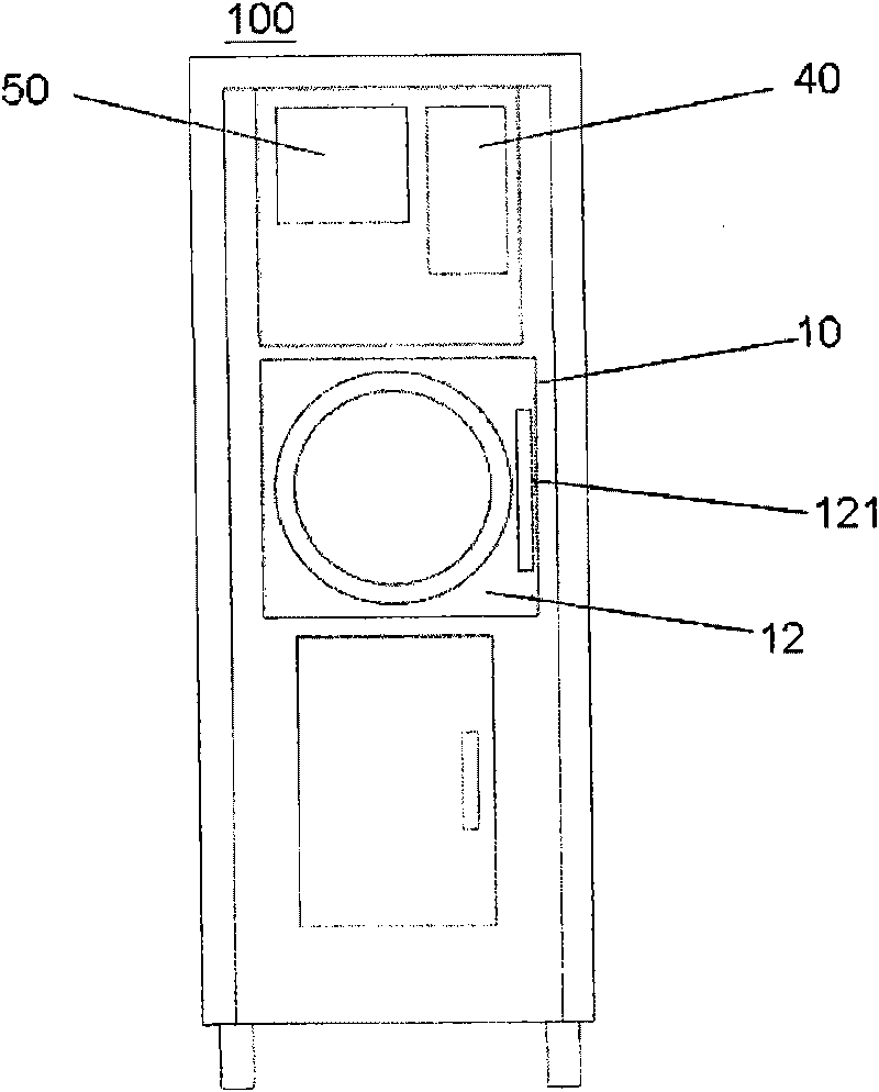
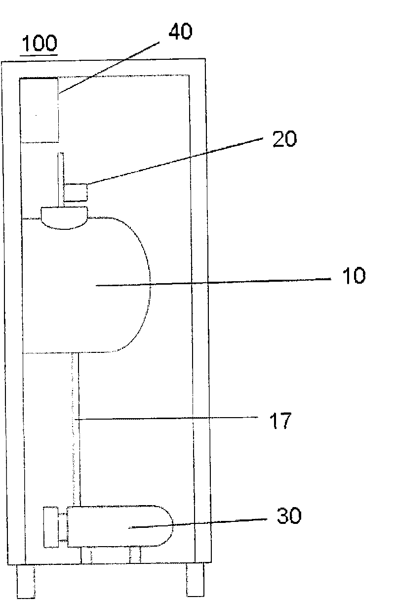
[0042] First, see Figure 2A and Figure 2B Shown is a front view and a side perspective view of a mask cleaning device of the present invention. and Figure 3A and Figure 3B , is a schematic front view and a schematic side view of the cavity of the above-mentioned mask cleaning device. The mask cleaning device 100 of the present invention includes a cavity 10, a photoelectric element 20, a pump system 30, and a controller 40, wherein the cavity 10 has an opening 11 and a cavity that can be sealed with the opening 11 The door 12 has a handle 121 on the chamber door 12 to facilitate the opening of the chamber door 12 . And inside the cavity 10 is a closed chamber 13, this closed chamber 13 is provid...


PUM


Abstract

The invention relates to a mask cleaning device, which at least comprises a cavity, a photoelectric element, a pump system and a controller. The cavity is provided with an airtight chamber, the airtight chamber is provided with a mask holder for bearing a mask, the mask is provided with a frame, and the frame is stuck with a layer of protective film; the photoelectric element is used for emitting a light beam to the protective film on the mask, receiving the light beam reflected from the protective film and transmitting a signal to represent fluctuating change of the protective film on the mask; the pump system is used for pumping off gases in the airtight chamber of the cavity to form negative pressure in the airtight chamber so as to separate contaminants on the mask; and the controller is used for receiving a signal of the photoelectric element, and the controller outputs another signal to stop operation of the pump system when the signal shows that the fluctuating change of the protective film on the mask is greater than a set value.

Description

technical field [0001] The present invention relates to a mask cleaning device and its cleaning method, in particular to a cleaning device that uses a vacuum method to clean the mask, and uses a photoelectric element to monitor the height of the protective film on the mask during the cleaning process ups and downs. Background technique [0002] In the semiconductor manufacturing process, the circuit pattern on the mask (reticle) is usually imaged completely and accurately on the photoresist on the wafer by lithography equipment and exposed. At the same time, some contaminants or particles will be generated, and the contaminants or particles will further contaminate the mask. Therefore, the organic substances, pollutants, chemical pollutants, etc. remaining on the surface of the mask must be cleaned efficiently and thoroughly during cleaning, otherwise the contaminated mask will cause product qualification (yield rate) in the subsequent process. ) serious losses. [0003] ...

Claims


Application Information

Patent Timeline
Patent Type & Authority Applications(China)
IPC IPC(8): G03F1/00B08B11/00G03F1/82
Inventor 邹本纬
Owner GUDENG PRECISION IND CO LTD
Why Eureka
Try Eureka