

Developing device
A developing device and developer technology, applied in electrography, optics, instruments, etc., can solve problems such as complicated manufacturing methods and blade gaps, and achieve the effects of suppressing extreme compression, suppressing damage, and reducing consumption
- Summary
- Abstract
- Description
- Claims
- Application Information
AI Technical Summary
Problems solved by technology
Method used
Image

Examples
Embodiment Construction
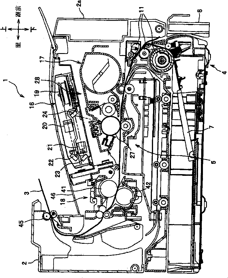
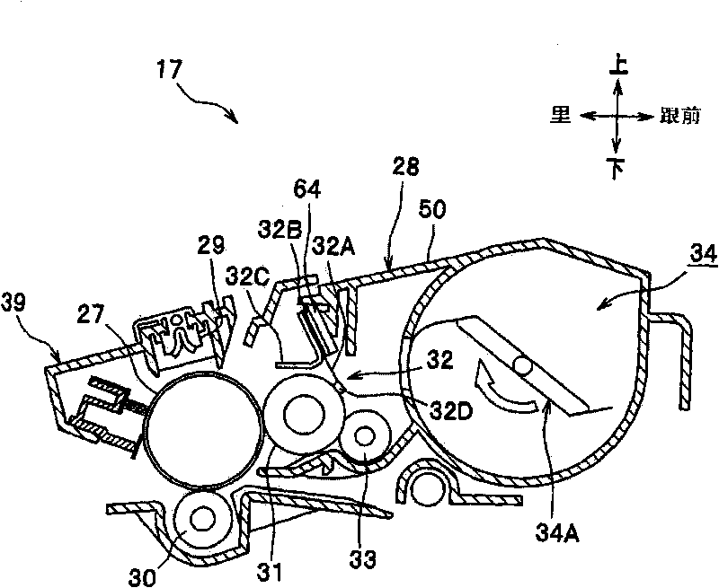
[0080] Hereinafter, a first embodiment of the present invention will be described in detail with appropriate reference to the drawings. In the referenced drawings, figure 1 is a side sectional view showing a laser printer having a developing cartridge according to an embodiment of the present invention, figure 2 is a side cross-sectional view showing the developer cartridge. In addition, in the following description, the overall structure of the laser printer will be briefly described first, and then the details of the characteristic parts of the present invention will be described.
[0081] In addition, in the following description, a user who uses the laser printer 1 as a reference will be used for description. That is, in figure 1 , the right side is referred to as "the front side (front side)", the left side is referred to as the "back side (rear side)", the rear side in the direction perpendicular to the paper surface is called the "right side", and the vertical paper...
PUM
 Abstract
Description
Claims
Application Information