
Flexible calibrating method and device for variable-format multiple-camera system

The technology of a calibration device and calibration method, which is applied in image data processing, television, instruments, etc., can solve the problems of difficulty in guaranteeing calibration accuracy, difficulty in application, complicated calibration process, etc., and achieve the effect of reducing the difficulty of manufacturing and improving the accuracy

Active Publication Date: 2010-06-09
新拓三维技术(深圳)有限公司
View PDF0 Cites 30 Cited by
  • Summary
  • Abstract
  • Description
  • Claims
  • Application Information

AI Technical Summary

Problems solved by technology

[0006] Early camera calibration methods required precise control of the relative motion between the camera and the calibration object, or precise knowledge of the geometric dimensions of the calibration object. This type of method can achieve high-precision calibration, but the calibration process is complex and difficult to apply in practice.
In 1998, Zhang Zhengyou proposed a camera calibration method based on a plane template based on the traditional calibration method, using the orthogonality condition of the rotation matrix and nonlinear optimization for camera calibration, with an accuracy of about 0.35 pixels and easy to implement. The field of vision has been widely used, but this method treats the plane template as an ideal plane, ignoring the manufacturing error of the template, in addition, it only considers two main distortion parameters, the calibration accuracy is difficult to guarantee, and can only be used for Calibration of small format cameras

Method used


Image

  • Flexible calibrating method and device for variable-format multiple-camera system
  • Flexible calibrating method and device for variable-format multiple-camera system
  • Flexible calibrating method and device for variable-format multiple-camera system

Examples


Embodiment Construction

[0034] The present invention will be further described in detail below in conjunction with the accompanying drawings and embodiments.

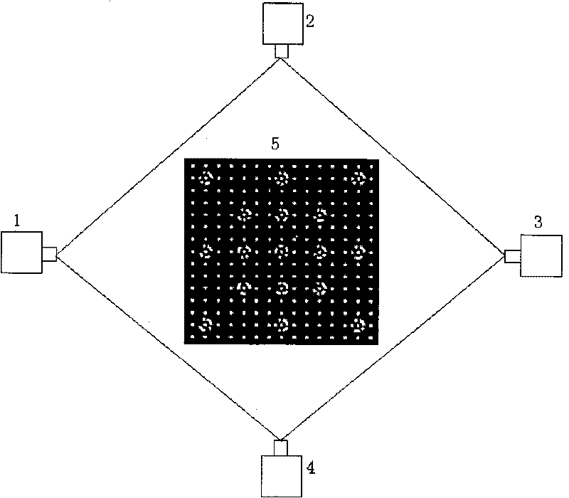
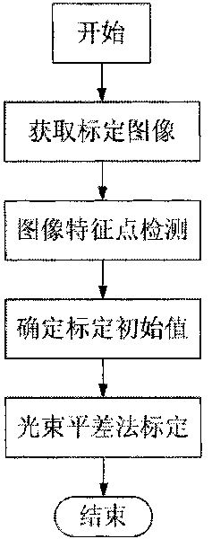
[0035] The present invention proposes a fast camera calibration method for a multi-vision system, the calibration device such as figure 1 As shown, 1, 2, 3, and 4 in the figure represent the cameras that make up the multi-camera system, and 5 represents the calibration template. The basic process is as follows figure 2 shown. In addition, the present invention independently develops matching calibration software based on the Visual C++6.0 platform.

[0036] A method for calibrating a variable-format multi-camera system proposed by the present invention is described as follows by taking the calibration of a multi-camera system with a field of view of 400mm*400mm*400mm as an example:

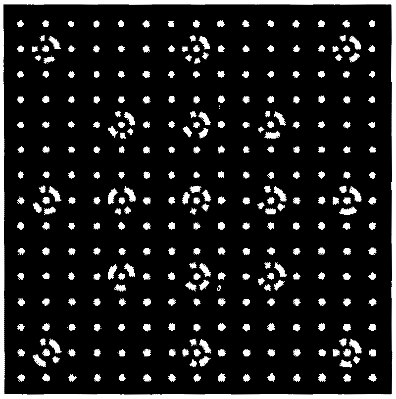
[0037] The first step is to obtain the calibration image: using such as figure 2 The calibration template with a format size of 400mm*400mm is shown. There a...


PUM


Abstract

The invention discloses a calibrating method for cameras of a multiple-camera system. The method comprises the following steps of: step 1. opening all cameras of the multiple-camera system, and collecting eight images of different positions and attitudes in a calibrating template; step 2. processing the collected images, and detecting the feature points of the images; step 3, utilizing a photogrammetric method to perform relative orientation and absolute orientation on the calibrating images to determine the initial values of the parameters to be calibrated in the cameras; step 4, performing optical beam adjustment calibration on the cameras according to the established cameral deformation model, realizing the optimized adjustment of the calibrating parameters, and finally performing temperature compensation on the calibrating results. Proved by experiments, the invention has the advantages of simple operation, practicality, flexibility and high precision.

Description

technical field [0001] The invention relates to the calibration problem of cameras in a computer vision system, in particular to a flexible calibration method and device for a variable-format multi-camera system. Background technique [0002] Multi-camera systems (including multi-camera systems and multi-camera systems) can be widely used in many fields such as 3D reconstruction, visual monitoring, motion analysis, and medical research. In a multi-camera system, the relationship between the three-dimensional information of the object surface point and the two-dimensional information of the corresponding point on the image is established through the camera model, and the camera model is determined by the internal and external parameters of the camera. The so-called calibration is to solve the internal and external parameters of the camera. The process of parameters, where the internal parameters refer to the focal length, feature ratio, distortion factor and principal point, ...

Claims


Application Information

Patent Timeline
IPC IPC(8): G06T7/00H04N17/00
Inventor 梁晋肖振中胡浩唐正宗史宝全郭翔
Owner 新拓三维技术(深圳)有限公司
Learn More