
Wafer detection device

A detection device and chip technology, which is applied in the direction of semiconductor/solid-state device testing/measurement, etc., can solve the problems of long scanning time for the cassette and affect the production capacity of the equipment, and achieve the effect of smooth lifting, increasing equipment production capacity, and reducing vibration

Active Publication Date: 2010-06-09
SHENYANG KINGSEMI CO LTD
View PDF0 Cites 3 Cited by
  • Summary
  • Abstract
  • Description
  • Claims
  • Application Information

AI Technical Summary

Problems solved by technology

[0005] In order to solve this problem, the purpose of the present invention is to provide a new wafer detection device, which solves the problems in the prior art that the scanning time of the wafer cassette is long and affects the production capacity of the equipment, etc.

Method used


Image

  • Wafer detection device
  • Wafer detection device
  • Wafer detection device

Examples


Embodiment Construction

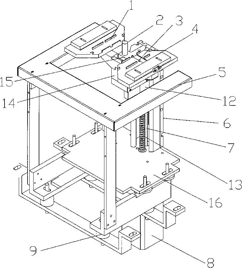
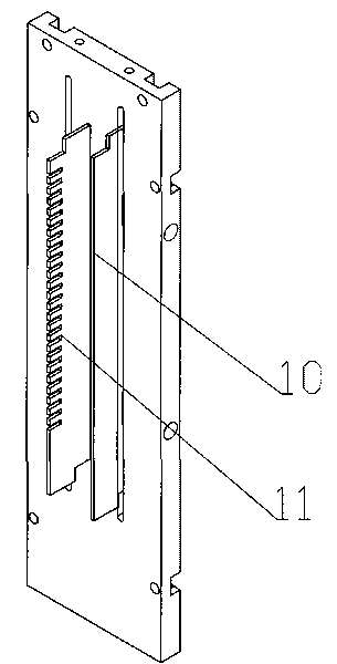
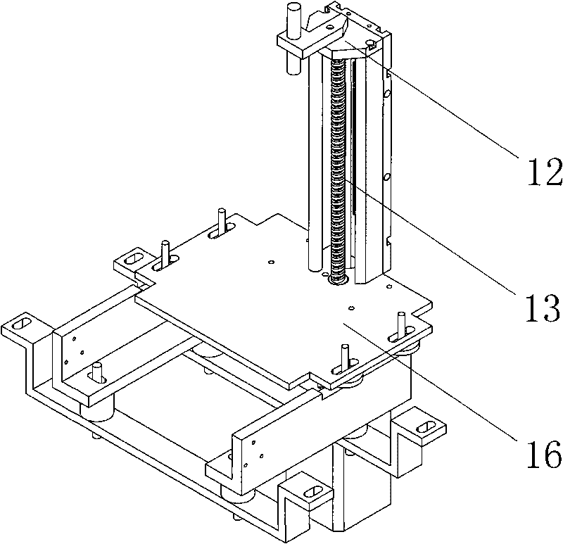
[0022] Such as Figure 1-Figure 2 As shown, the wafer detection device of the present invention mainly includes a wafer carrier, a proximity switch 2, a pressure switch 3, a support 5, a code disc device 6, a screw drive device 7, a motor 8, and a buffer pad 9, and the wafer carrier is a wafer carrier I 1. The chip holder II 4 is relatively arranged on the base 14. The bottom of the base 14 is provided with a screw drive 7. The screw drive 7 is formed by a supporting ball screw 13 and a nut 12. The base 14 and the screw The nut 12 of the transmission device 7 is connected, the screw seat 15 on the top of the ball screw 13 is equipped with a proximity switch 2, the proximity switch 2 is located between the film holder I1 and the film holder II4, and the motor 8 is driven by the transmission shaft and the lead screw. The ball screw 13 of the device 7 is connected. Lead screw transmission device 7 can be installed on the base plate 16 of support 5, and buffer pad 9 is equipped w...


PUM


Abstract

The invention relates to the technology of scanning and recording semiconductor wafers in the process of processing the wafers, in particular to a wafer detection device. The wafer detection device records numbers and positions of the wafers to be processed in a wafer box and solves the problems of long time for scanning the wafer box, influence on equipment capacity and the like in the prior art. The device is provided with wafer holding platforms, a proximity switch, a pressure switch, a bracket, a coded disk device and a screw driving device, wherein the wafer holding platforms are a wafer holding platform I and a wafer holding platform II oppositely arranged on a base; the bottom of the base is provided with the screw driving device which consists of a ball screw and a matched nut; the base is connected with the nut of the screw driving device; and a screw base on the top of the ball screw is provided with the proximity switch which is positioned between the wafer holding platform I and the wafer holding platform II. The wafer detection mode can reduce detection time and improve productivity.

Description

technical field [0001] The invention relates to the technology of scanning and recording wafers during semiconductor wafer processing, in particular to a wafer detection device which records the number and position of wafers in the processed wafer cassette. Background technique [0002] As we all know, in fully automatic semiconductor equipment, it is necessary to scan the cassettes in which wafers are placed to determine the number of wafers in the cassette and their storage locations. In this way, the manipulator responsible for wafer delivery can accurately deliver it to each module for processing the wafer. [0003] The original wafer scanning method is as follows: a light-emitting device and a light-receiving device are respectively installed at the front and rear of the cassette, and the cassette is loaded on a liftable device. In this way, the film box lifting mechanism is driven to move from top to bottom by the rotation of the motor. When there are wafers in the f...

Claims


Application Information

Patent Timeline
IPC IPC(8): H01L21/66
Inventor 侯宪华
Owner SHENYANG KINGSEMI CO LTD
Learn More