Grounding device of metal-clad moveable high-voltage switchgear

A high-voltage switchgear and grounding device technology, applied in the direction of the grounding device of the switchgear, can solve the problems of large grounding resistance, potential safety hazards for operators, complex structure, etc., and achieve the effects of reducing contact resistance, ensuring safety, and superior grounding performance

Inactive Publication Date: 2010-06-09
ANHUI ZHONGDIAN XINGFA & XINLONG TECH CO LTD
View PDF0 Cites 5 Cited by
  • Summary
  • Abstract
  • Description
  • Claims
  • Application Information

AI Technical Summary

Problems solved by technology

[0004] However, in the prior art, the cabinet grounding device has a relatively complicated structure, and some of them rely on the circuit breaker or the four wheels on the

Method used


Image

  • Grounding device of metal-clad moveable high-voltage switchgear
  • Grounding device of metal-clad moveable high-voltage switchgear
  • Grounding device of metal-clad moveable high-voltage switchgear

Examples


Embodiment 1

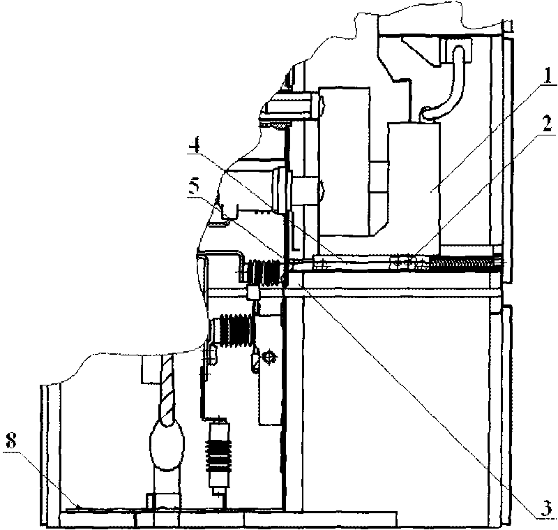
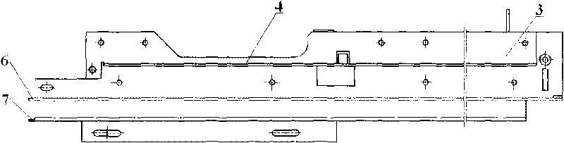
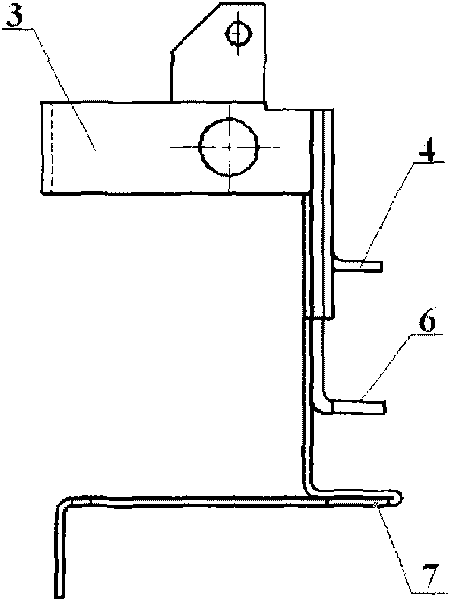
[0041] Such as Figure 1 to Figure 5 As shown, the guide rail 3 of the present invention is provided with a guide rail grounding copper bar 4, the guide rail grounding copper bar 4 is parallel to the guide rail 3, and the handcart 1 is provided with a duckbill ground contact 2, The duckbill ground contact 2 is provided with an elastic clamping structure. Through the elastic clamping structure, the duckbill ground contact 2 is clamped on the rail ground copper bar 4.

[0042] The duckbill ground contact 2 is a clamp-shaped structure with an elastic clamping structure, and the jaws clamp the rail grounding copper bar 4. A perfect grounding circuit is formed as follows:

[0043] Duckbill grounding contact 2-rail grounding copper bar 4-grounding conductor 5-main grounding bar 8.

[0044] The duckbill grounding method on both sides of the handcart 1 is completed by the cooperation of the duckbill grounding contact 2 and the guide rail grounding copper bar 4. The handcart 1 is in the sli...

Embodiment 2

[0053] Such as Image 6 , Figure 7 with Figure 8 As shown, the present invention adopts a front duckbill grounding method:

[0054] That is, the front end of the handcart 1 is provided with a grounding movable plug 9, and the cabinet body of the high-voltage switch cabinet is provided with an elastic duckbill contact 10. When the handcart 1 is running to the working position, the elastic The duckbill contact 10 clamps the grounding movable plug 9 under the action of elastic force.

[0055] The front duckbill type grounding method is completed by the cooperation of the elastic duckbill contact 10 and the grounding movable plug 9, and the elastic duckbill type contact 10 and the grounding movable plug 9 adopt two pairs. When the handcart 1 reaches the working position, the elastic duckbill contact 10 and the grounding movable plug 9 are closely snapped together to ensure the good grounding of the switchgear.

Embodiment 3

[0057] Such as Picture 9 , Picture 10 with Picture 11 As shown, the present invention adopts a spring static pressure grounding method:

[0058] That is, the cabinet handcart room of the high-voltage switchgear is equipped with a middle-level partition 11, and a partition grounding bar 12 is arranged on the middle-level partition 11, and the direction of the partition grounding bar 12 is the same as that of the handcart 1. The operating direction of the handcart 1 is the same, and the handcart 1 is provided with a grounding elastic pressure contact 13 which is clamped on the partition grounding bar 12.

[0059] The spring static pressure grounding method is completed by the cooperation of the grounding elastic pressure contact 13 and the diaphragm grounding bar 12, and two pairs of the diaphragm grounding bar 12 and two grounding elastic pressure contacts 13 are used. During the sliding process of the handcart 1 from the test position to the working position and when it reaches ...


PUM


Abstract

The invention discloses a grounding device of a metal-clad moveable high-voltage switchgear, which comprises a handcart (1) and guide rails (3) arranged on a body of a switchgear for the handcart (1) to run on, wherein the handcart (1) and the grounding device of the high-voltage switchgear adopt a clamp type connection structure. According to the technical scheme, when the handcart is swung to a work position from a test position by a swing mechanism, the grounded connection structures are tightly occluded together in a gliding process or a work state, so the contact resistance is greatly reduced, the safety of operators is further guaranteed and the requirements on electric grounding safety of the switchgear are completely met. The combined use of a plurality of grounding ways makes the grounding performance of the grounding device of the metal-clad moveable high-voltage switchgear; and the plurality of grounding ways can be freely and flexibly selected.

Description

Technical field [0001] The invention belongs to the technical field of power equipment, and relates to the structure of a power switch cabinet. More specifically, the invention relates to a metal armored removable high-voltage switch cabinet grounding device. Background technique [0002] In the current power system, there have been reports on the development of metal armored removable high-voltage switchgear, and its structure and function are also different. The high-voltage switchgear adopts armored removable AC enclosed switchgear of PT handcart equipped with vacuum circuit breaker and detecting bus voltage. [0003] Handcarts are the main components in the withdrawable switchgear. Generally, there are PT handcarts and switch (circuit breaker) handcarts. The handcart is also called a trolley. Take the switch handcart as an example. When the switch is disconnected, it can be pulled out of the switch cabinet by hand after laying the guide rails for maintenance or replacement. I...

Claims


Application Information

Patent Timeline
IPC IPC(8): H02B11/28
Inventor 束龙胜李开明宛玉超孙国才汪桂林孟祥军付强王标周波张攀科杨成长刘建桂召凡
Owner ANHUI ZHONGDIAN XINGFA & XINLONG TECH CO LTD
Why Eureka
Try Eureka