Motor

A technology of armature and winding, applied in the direction of electric steering mechanism, electrical components, electromechanical devices, etc., can solve the problems of increased manufacturing cost, deterioration of winding space factor, and deterioration of productivity, and achieve the effect of increasing torque

Inactive Publication Date: 2010-06-09
JTEKT CORP
View PDF1 Cites 11 Cited by
  • Summary
  • Abstract
  • Description
  • Claims
  • Application Information

AI Technical Summary

Problems solved by technology

[0006] However, since two windings are respectively wound on each tooth by the concentrated winding method, there is a problem that the manufacturing cost increases due to deterioration of productivity compared with the case of winding one winding by the concentrated winding method.
In addition, since the number of lead wires drawn from the winding per tooth is doubled, the space factor of the winding is also deteriorated in addition to the workability, which becomes an obstacle to the miniaturization of the motor.

Method used


Image

  • Motor
  • Motor
  • Motor

Examples


Embodiment Construction

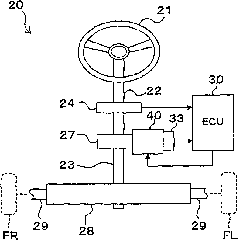
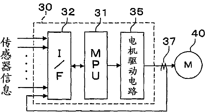
[0026] [16] Hereinafter, a first embodiment of the present invention will be described with reference to the drawings. First, based on Figure 1A The configuration of the electric power steering apparatus 20 using the motor 40 according to the first embodiment will be described. Figure 1A is a configuration diagram showing an example of the overall configuration of the electric power steering device according to the first embodiment of the present invention, Figure 1B It is a circuit block diagram showing a configuration example of the ECU 30 and the like.

[0027] [17] The electric power steering device 20 is mainly composed of a steering wheel 21, a steering shaft 22, a pinion input shaft 23, a steering wheel angle sensor 24, a reducer 27, a rack and pinion mechanism 28, a pull rod 29, an ECU 30, and a motor rotation angle The sensor 33, the motor 40, etc. constitute.

[0028] [18] If Figure 1A As shown, one end of the steering shaft 22 is connected to the steering wh...


PUM


Abstract

A motor (40) includes twelve stator teeth (52) arranged at equal intervals in the circumferential direction. A three phase first coil group (Sa) is formed by star-connecting of coils (S 1 , S 3 , S 5 , S 7 , S 9 and S 11 ) formed on the odd-numbered teeth (52), and a three phase second coil group (Sb) is formed by delta-connecting coils (S 2 , S 4 , S 6 , S 8 , S 10 and S 12 ) formed on the even-numbered teeth (52), the first coil group (Sa) and the second coil group (Sb) are connected in parallel.

Description

technical field [0001] The present invention relates to electric machines. Background technique [0002] As a motor for assisting steering in an electric power steering apparatus, for example, a motor disclosed in Japanese Patent Application Laid-Open No. 2007-221961 described below is known. The motor is a three-phase, ten-pole, twelve-tooth motor. In its armature, two windings are respectively wound on the same tooth in a concentrated winding manner. The two windings flow U / V / W three-phase AC different from each other phase current. [0003] Thereby, the magnetomotive force vector of the low-order component of the spatial 5th order component whose order is lower than that of the synchronous component of the armature magnetomotive force (winding magnetomotive force) is dispersed, and the resulting vector is reduced. By reducing the resultant vector of low-order components in the armature magnetomotive force in this way, the eddy current loss of the magnetic field poles is...

Claims


Application Information

Patent Timeline
Patent Type & Authority Applications(China)
IPC IPC(8): H02K3/18H02K3/28H02K29/06H02P6/16B62D5/04
CPCH02K21/16H02K3/28
Inventor 山口茂利
Owner JTEKT CORP
Why Eureka
Try Eureka