Power switching device

A power conversion device and power conversion technology, which are applied in the direction of output power conversion device, cooling/ventilation of substation/switchgear, board/panel/desk of substation/switchgear, etc., can solve the limitation of freedom of installation position, storage The unit space in the casing is small and the cooling air leaks, etc., to achieve the effect of increasing the degree of freedom, improving the cooling effect, and reducing the shape of the casing

Active Publication Date: 2010-06-09
FUJI ELECTRIC CO LTD
View PDF1 Cites 12 Cited by
  • Summary
  • Abstract
  • Description
  • Claims
  • Application Information

AI Technical Summary

Problems solved by technology

Therefore, a space is required in the panel for the cooling air to flow in the vertical direction, constituting the installation position of the equipment is restricted, and there is a problem that the degree of freedom of the installation position is limited.
In addition, in the conventional power conversion device, the cooling air exhaust port provided on the top plate cannot be easily changed. Therefore, when the upper part is connected to the outside, it is only for wiring, and it must be installed on the upper part of the panel for arranging the outside. Problems with other pads connecting the terminals
[0020] In addition, in the conventional power conversion device, the connection work between the units is performed on the back side of the case, or each unit is pulled out to the front side of the case, and it is performed on the front side, which has a problem in terms of efficiency in the connection work between the units.
[0021] In addition, there are many wirings on the back side of the case, the amount of wiring increases, and there is also a problem that the space for storing the units in the case is small.
[0022] In addition, in the unit that constitutes the uninterruptible power supply device like the conventional device, for example, the reactor that suppresses the high-frequency component of the alternating current is connected to other units with a large number of wires, so the cooling that flows in the unit by the cooling fan on the unit side Wind leaks to the outside of the unit and cannot be completely avoided
Therefore, there is a problem that a sufficient cooling effect cannot be obtained for a unit with a large number of wires connected to other units such as a reactor.

Method used


Image

  • Power switching device
  • Power switching device
  • Power switching device

Examples


Embodiment Construction

[0073] A first embodiment of the present invention will be described below with reference to the drawings.

[0074] Figure 1 ~ Figure 3 The configuration of an embodiment of the power conversion device panel of the present invention is shown.

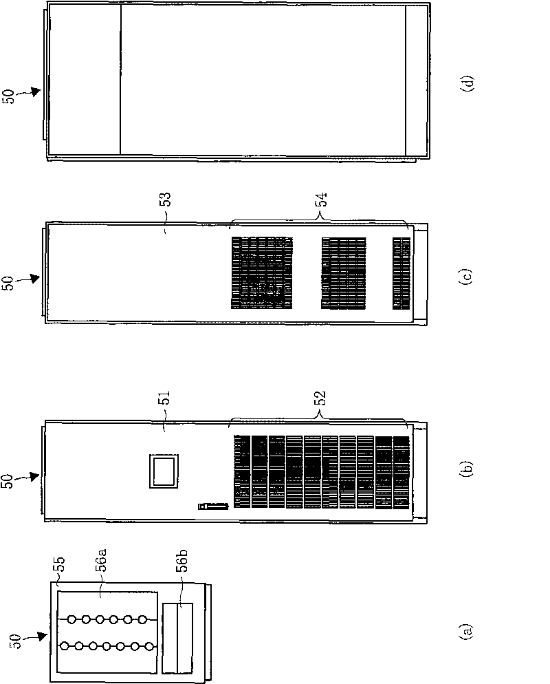
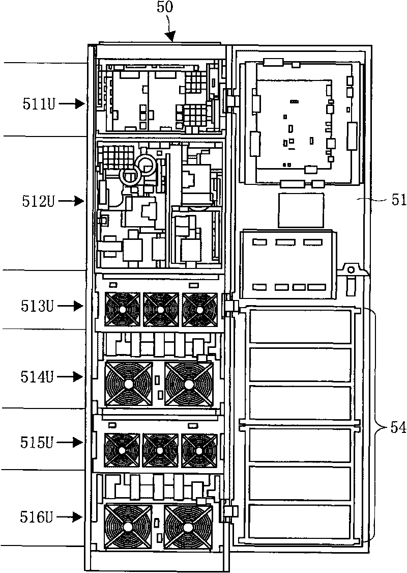
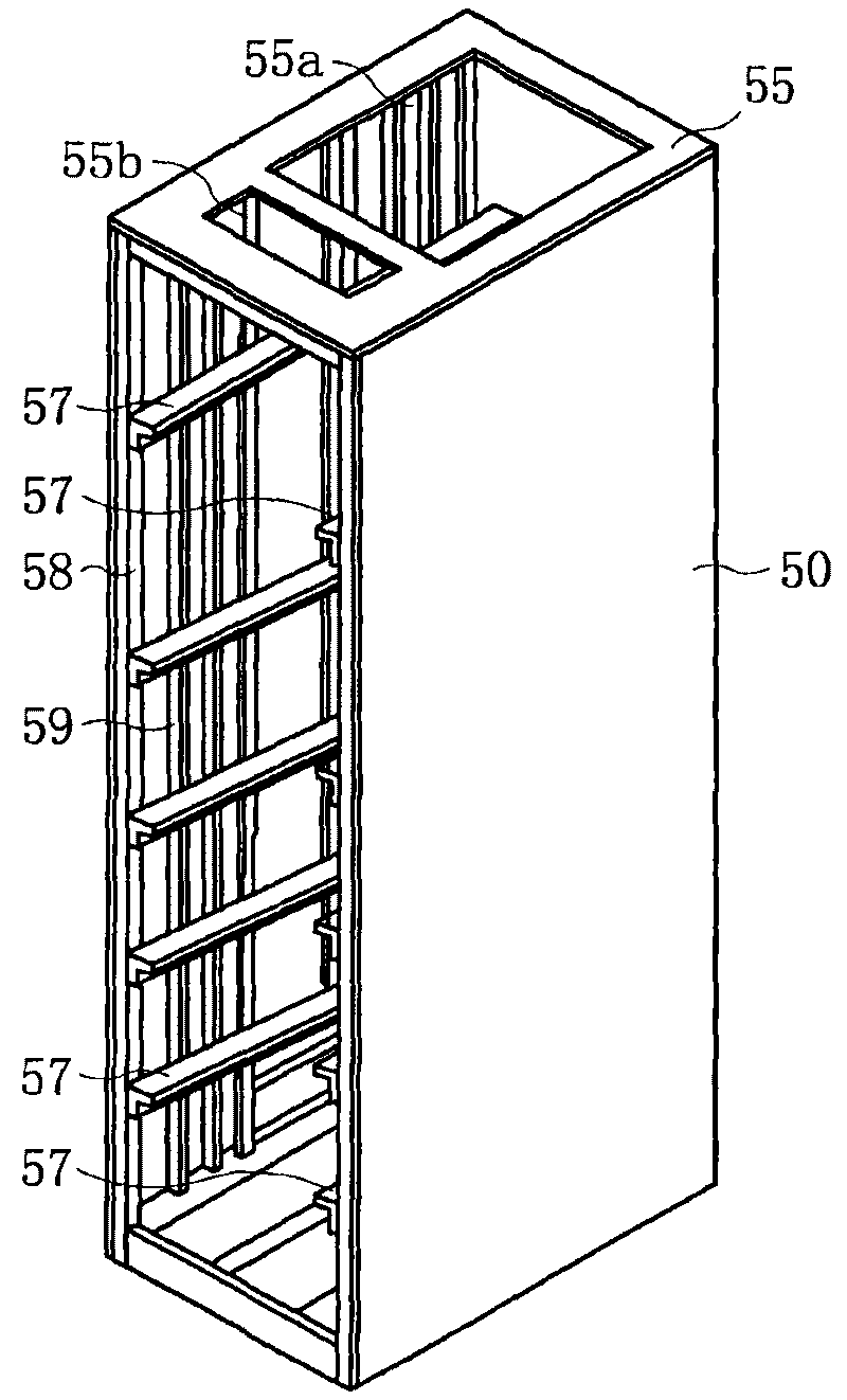
[0075] figure 1 (a) is a front view, (b) is a back view, (c) is a plan view, and (d) is a side view, showing the appearance of a disk. figure 2 It is the front view showing the state that opened the door of the tray. image 3 It is a perspective view which shows the structure of a disk main body.

[0076] In the above-mentioned figures, reference numeral 50 denotes a grid-like disk main body, and reference numeral 51 denotes an openable and closable front door provided at the front opening. In the substantially lower half of the front door 51, there is a vent 52 with a grid-shaped opening, from which outside air is sucked into the tray as cooling air (refer to figure 1 (a)). On the rear cover 53 of the disk, at a position faci...


PUM


Abstract

The invention provides a power switching device with high selection freedom comprising an installation position of a terminal for connecting an outer wire and installation position of each device. One ventilator for sucking and exhausting the cool wind is respectively arranged on a door of a fence disk main body and an opposite back plate and a plurality of unit housings are inserted into many segments of the lamination layers along the vertical direction in the disk main body and a device housed in the disk main body and forming the power switching device is divided into many sets according to the function and each set of the devices is housed in the unit housing according the sets to form a plurality of function units. A function unit of the device in need of being cooled is arranged in the function unit and a cooling fan is arranged before the unit housing to freezing the unit housing from the front surface to the back and the function unit of the device in need of being cooled is inserted into the position opposite to the ventilator in the fence disk main body and the other function units are inserted into arbitrary position.

Description

technical field [0001] The present invention relates to a power conversion device, in which a power converter such as a converter (converter) and an inverter (inverter) constituted by semiconductor elements, such as an uninterruptible power supply device, and a circuit breaker for performing power switching and protection are carried out. Various electrical equipment such as contactors for circuit selection switching and filter reactors are housed in a cubicle body. Background technique [0002] Figure 15 Shows the general circuit configuration of an uninterruptible power supply unit. [0003] exist Figure 15 Among them, the AC power from the commercial frequency power supply 1 passes through the circuit breaker 27, the contactor 211, the filter 215, and then enters the power converter 24. The power converter 24 is composed of a converter 241 that converts AC power into DC power and the DC An inverter 242 is configured for converting electric power into AC electric power ...

Claims


Application Information

Patent Timeline
Patent Type & Authority Applications(China)
IPC IPC(8): H02M1/00H02B1/56H05K7/20H02B1/20H02B1/04
Inventor 石井纪好
Owner FUJI ELECTRIC CO LTD
Why Eureka
Try Eureka