Power circuit

A power circuit and control circuit technology, applied in circuit devices, emergency power supply arrangements, high-efficiency power electronic conversion, etc., can solve the problems of increasing installation area, large size, and high price of current transformers, achieving miniaturization and reducing parts. The number of pieces, the effect of realizing high efficiency

Inactive Publication Date: 2010-06-09
YUTAKA ELECTRIC MFG
View PDF1 Cites 6 Cited by
  • Summary
  • Abstract
  • Description
  • Claims
  • Application Information

AI Technical Summary

Problems solved by technology

[0007] On the other hand, the size of the current transformer is, for example, 30mm x 30mm, which is large in size and requires an increase in the mounting area, so there is a problem that it hinders the miniaturization of the entire power supply circuit.
In addition, since the price of the current transformer is high, there is a problem that it also hinders the reduction of the price of the product.

Method used


Image

  • Power circuit
  • Power circuit
  • Power circuit

Examples


Embodiment 1

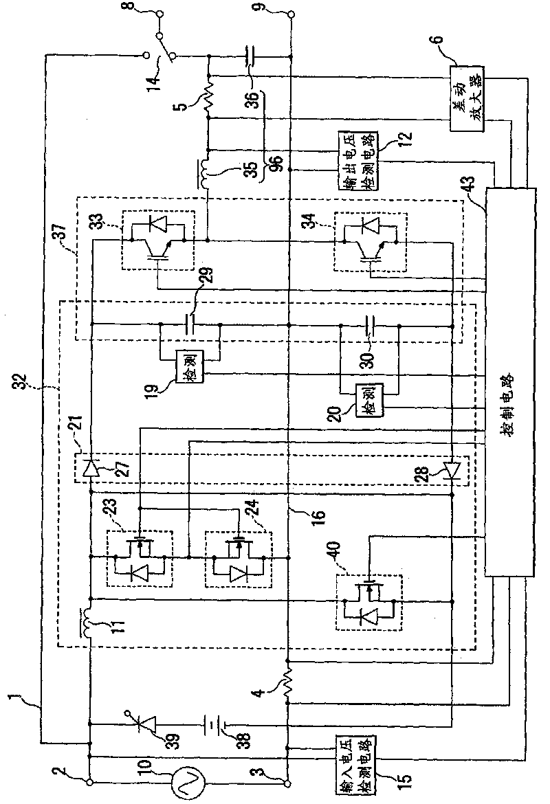
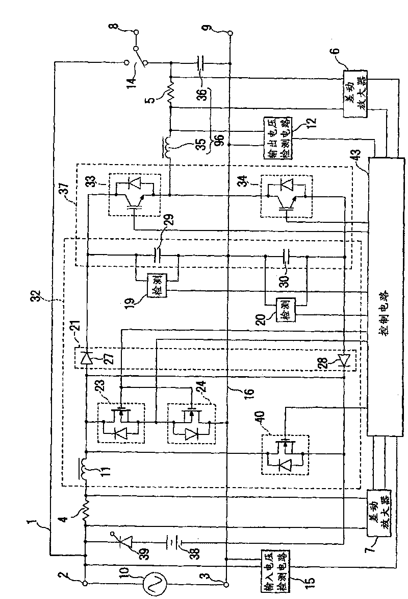
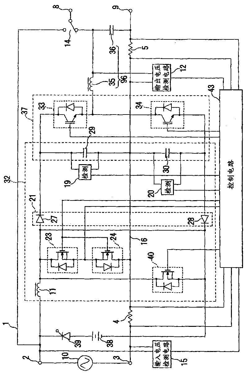
[0062] according to figure 1 The shown circuit diagram explains the structure of the power supply circuit of the present invention. exist figure 1 Among them, 2 and 3 are AC input terminals for connecting the AC power supply 10, respectively, and 8 and 9 are respectively stabilized AC output terminals. One AC input terminal 3 and one AC output terminal 9 among these input and output terminals are directly connected by the common line 16 , and the other AC input terminal 2 and the other AC output terminal 8 are connected via the direct transmission line 1 and the switching circuit 14 . between, thus forming a direct transmission circuit.

[0063] Between the above-mentioned AC input terminals 2 and 3, the input voltage detection circuit 15 and the boost chopper circuit and the power factor improvement filter 32 are connected, and the boost chopper circuit also serves as the power factor improvement filter 32. In the latter stage, the DC-AC inverter 37 , the filter circuit ...

example 1

[0085] figure 2 A configuration example 1 of the input current detection resistor 4 and the output current detection resistor 5 which is different from the present invention is shown. in the figure 2 In configuration example 1 shown, in Figure 5 The input current detection resistor 4 is arranged at the position in which the current transformer 17 is arranged, and the output current detection resistance 5 is arranged between the reactor 35 and the capacitor 36 constituting the output filter 96 . In addition, in the case of performing such an arrangement, in order to remove the adverse effect due to the noise from the input side and to match the control circuit 43 to the ground point, it is necessary to use the differential amplifiers 6 and 7 to pass through the control circuit respectively. 43 A structure for inputting input voltage and output voltage information.

[0086] According to the figure 2 In the arrangement example 1 shown, the input voltage and output voltage ...


PUM


Abstract

The invention provides a power circuit capable of reducing the installation area and realizing the low cost of the product without a current transformer. The alternating voltage input between a common line and another input terminal is subjected to voltage-increasing chopping under the control of a control circuit in a voltage-increasing chopping device circuit and a filter for power factor improvement, therefore voltage-increased direct voltage with improved power factor is obtained at the positive side and the negative side of the common line and the stable direct voltage is changed into the alternating voltage by a half-bridge type DC-AC inverter at the back stage and the high-frequency component is removed by an output filter composed of a reactor and a capacitor and the voltage is output and an input current detection resistance is arranged at the front stage of the switching element on the common line and an output current detection resistance is arranged between the input side of the reactor for composing the output filter or the reactor and the capacitor.

Description

technical field [0001] The present invention relates to a power supply circuit, and more particularly, to an AC stabilized power supply circuit with improved power factor and a power supply circuit without blackout. Background technique [0002] Conventionally, various circuits have been proposed as a power factor improvement type stabilized power supply circuit in which one of the AC input line and the output line is combined as a common line. For example, in Patent Document 1, the applicant of the present patent has proposed that Figure 5 power circuit shown. [0003] Should Figure 5 The power supply circuit shown is proposed in view of the problem of wasteful generation of power consumption in the conventional power supply circuit, and the purpose is to provide a circuit that suppresses power consumption and achieves high efficiency and miniaturization without increasing the number of parts. power circuit. According to the Figure 5 In the power supply circuit of the ...

Claims


Application Information

Patent Timeline
Patent Type & Authority Applications(China)
IPC IPC(8): H02M5/40H02M5/453H02M1/42
CPCH02J9/062Y02B70/126H02J2009/063H02M1/4208H02M5/458H02J9/063Y02B70/10Y02P80/10
Inventor 菅野充
Owner YUTAKA ELECTRIC MFG
Why Eureka
Try Eureka