Communication equipment, communication system and method for controlling uplink transmission power

A transmission power control and transmission power technology, applied in the field of uplink transmission power control and communication equipment, can solve the problems of lack of service, no further adjustment, terminal performance impact, etc., and achieve the effect of accurate adjustment

Inactive Publication Date: 2010-06-09
HUAWEI TECH CO LTD
View PDF0 Cites 25 Cited by
  • Summary
  • Abstract
  • Description
  • Claims
  • Application Information

AI Technical Summary

Problems solved by technology

[0005] During the research and practice of the prior art, the inventors of the present invention found that the interference signal strength generated by the terminal to the terminal within the coverage of the base station is around the interference signal strength threshold I of the base station th Fluctuates in a small range up and down, so the interference generated by the terminals in the coverage area of ​​the base station tends to be the same, which leads to the interference degree of the terminals in the coverage area of ​​the base station depends on the load level of the adjacent base stations of the base station, such as The number of terminals that cause interference, the more terminals that interfere with them, the more serious the interference will be. At this time, the uplink transmission power of the terminals will not be further adjusted, and eventually the performance of the terminals within the coverage of the base station will be affected. Affected, can not get better service

Method used


Image

  • Communication equipment, communication system and method for controlling uplink transmission power
  • Communication equipment, communication system and method for controlling uplink transmission power
  • Communication equipment, communication system and method for controlling uplink transmission power

Examples


Embodiment 1

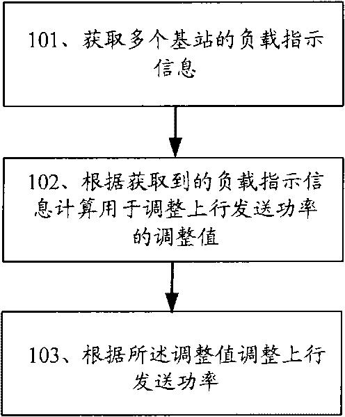
[0053] A method for controlling uplink transmission power. Firstly, load indication information of multiple base stations is obtained, an adjustment value for adjusting uplink transmission power is calculated according to the acquired load indication information, and then uplink transmission power is adjusted according to the adjustment value.

[0054] It should be noted that the subject of this action can be a terminal or a base station. When the subject of this action is a terminal, the terminal can know the load of multiple base stations by receiving the broadcast message from the base station or the message sent by the upper layer protocol configuration. Indication information; when the subject of the action is a base station, the base station can obtain load indication information of multiple adjacent base stations of the base station through terrestrial network transmission. Of course, the premise is that each base station will send its own load indication information and...

Embodiment 2

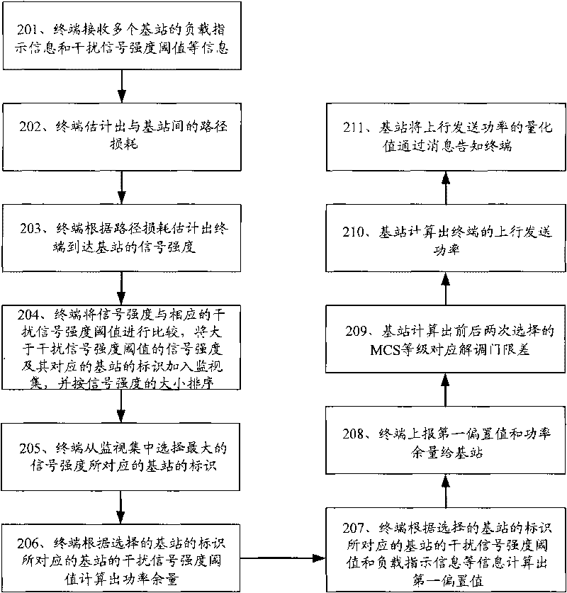
[0061] According to the method described in Embodiment 1, an example will be given below for further detailed description.

[0062] In this embodiment, the terminal is used as the execution subject of the action, that is, the terminal obtains the load indication information of multiple base stations, calculates the adjustment value for adjusting the uplink transmission power according to the obtained load indication information, and then adjusts the uplink transmission power according to the adjustment value. The transmission power will be described as an example.

[0063] First, the terminal calculates the signal strengths arriving at the multiple base stations according to the obtained interference signal strength thresholds of the multiple base stations, and then judges whether the signal strengths are greater than the interference signal strength thresholds of the corresponding base stations, and if not, considers that it is possible Ignore, do not process; if yes, add the...

Embodiment 3

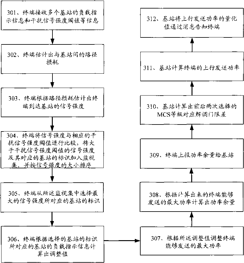
[0087] The difference between this embodiment and the second embodiment is that the load indication information is taken into account when calculating the maximum power that can be transmitted, that is, the adjustment value can be calculated according to the load indication information of the base station corresponding to the selected maximum signal strength, Then adjust the maximum power that the terminal can transmit according to the adjustment value, and finally calculate the uplink transmission power according to the adjusted maximum power that the terminal can transmit. In this way, the current channel condition can be better matched when the MCS level is selected, and the interference level of terminals within the coverage of the base station can be controlled more accurately.

[0088] Such as image 3 As shown, the specific process can be as follows:

[0089] 301. The terminal receives the interference signal strength threshold I of multiple base stations th , pilot / p...


PUM


Abstract

The invention discloses communication equipment, a communication system and a method for controlling uplink transmission power. In the embodiment of the invention, the method comprises the following steps of: obtaining load indication information of a plurality of base stations; calculating an adjusting value for adjusting the uplink transmission power according to the load indication information; and adjusting the uplink transmission power according to the adjusting value; or the method comprises the following steps of: obtaining a second interfering signal intensity threshold value of the plurality of base stations; and calculating the uplink transmission power according to second interfering signal intensity threshold value, wherein the second interfering signal intensity threshold value is obtained through each base station by adjusting the interfering signal intensity threshold value thereof according to the loading degree. Since the scheme provided by the invention takes the load indication information of the base stations into consideration while controlling the uplink transmission power, the problem that the uplink transmission power is not further adjusted when the loads of the base stations are too high is avoided. Therefore, the method can adjust the uplink transmission power of a terminal more correctly and improve the performance of the terminal in a covering surface of the base stations.

Description

technical field [0001] The present invention relates to the technical field of communication, in particular to a communication device, a communication system and an uplink transmission power control method. Background technique [0002] Orthogonal Frequency Division Multiple Access (OFDMA: Orthogonal Frequency Division Multiple Access) technology is a transmission technology that divides a channel into several orthogonal sub-channels, and then transmits data on the sub-channels. In an OFDMA system, terminals within the coverage of the same base station occupy different subchannels to transmit data on the uplink, that is, the link from the terminal to the base station. Since different subchannels are orthogonal to each other, the same base station Interference between terminals within the coverage area will be very small and can be ignored. However, the sub-channels occupied by terminals in the coverage of different base stations may not be orthogonal, so they may interfere ...

Claims


Application Information

Patent Timeline
Patent Type & Authority Applications(China)
IPC IPC(8): H04B7/005H04B7/26
Inventor 余劲童剑飞王学寰
Owner HUAWEI TECH CO LTD
Why Eureka
Try Eureka