
Minimally invasive intervertebral fusion cage and implanting device

An intervertebral fusion cage and an introduction device technology are applied in the field of instruments for intervertebral fusion surgery to achieve the effects of applying force and positioning accurately, simplifying operation steps and increasing stability

Inactive Publication Date: 2010-06-16
FARMAR LICENSING
View PDF2 Cites 9 Cited by
  • Summary
  • Abstract
  • Description
  • Claims
  • Application Information

AI Technical Summary

Problems solved by technology

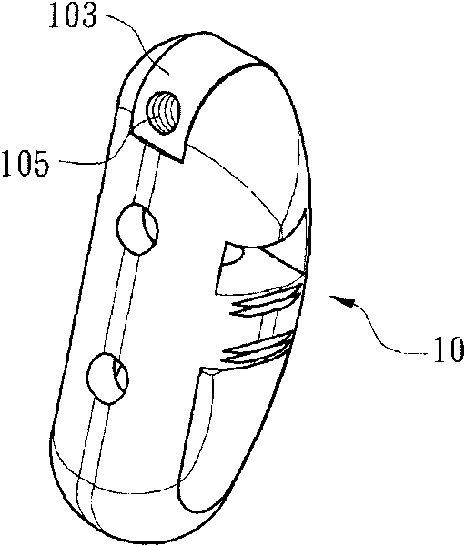
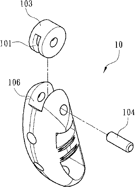
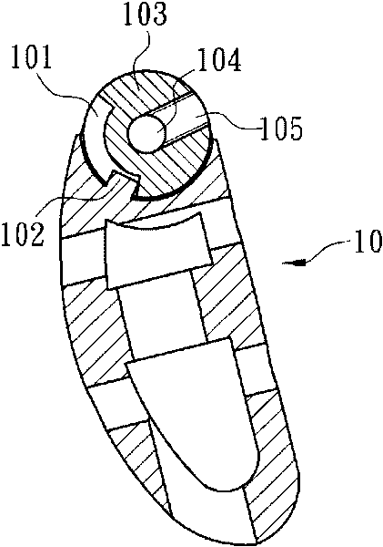
[0006]The purpose of the present invention is to overcome the existing known intervertebral fusion device and introduction device, the fusion device cannot be implanted in the intervertebral space at an ideal angle and position, The instability of the intervertebral region and the large surgical wound affect the recovery time of the patient. To provide a new structure of minimally invasive intervertebral fusion device and introduction device, the technical problem to be solved is to make the spinal fusion The instrument can place the fusion device in the intervertebral area at an ideal angle, so that the intervertebral pressure is evenly distributed, and only a small wound will be left on the affected area, which meets the purpose of minimally invasive surgery and makes up for the gap between the existing known intervertebral fusion instruments and introduction devices. Insufficient, very suitable for practical

Method used


Image

  • Minimally invasive intervertebral fusion cage and implanting device
  • Minimally invasive intervertebral fusion cage and implanting device
  • Minimally invasive intervertebral fusion cage and implanting device

Examples


Embodiment Construction

[0043] In order to further explain the technical means and effects adopted by the present invention to achieve the intended purpose of the invention, the specific implementation and structure of the minimally invasive intervertebral fusion device and the introduction device proposed according to the present invention will be described below in conjunction with the accompanying drawings and preferred embodiments. , features and their effects are described in detail below.

[0044] The aforementioned and other technical contents, features and effects of the present invention will be clearly presented in the following detailed description of the preferred embodiments with reference to the drawings. Through the description of the specific implementation mode, a more in-depth and specific understanding of the technical means and effects adopted by the present invention to achieve the intended purpose can be obtained. However, the accompanying drawings are only for reference and desc...


PUM


Abstract

The invention relates to a minimally invasive intervertebral fusion cage and an implanting device. The implanting device comprises a chambering instrument set, a fusion case, a guide rail tube and a guiding instrument set, wherein the chambering instrument set expands an intervertebral space; the fusion case is implanted between vertebras; the guide rail tube guides the fusion cage; the guiding instrument set pushes the fusion cage from the guide rail tube to the intervertebral space; a pivoting groove for accommodating a rotating ring is arranged on one side of the fusion cage; a pivoting pin inserts into the axes of the rotating ring so that the rotating ring is connected with the pivoting groove, and the rotating ring is annularly provided with a first limiting part and a first pivoting part which is connected with the guiding instrument set; and when the rotating ring forms a rotation relationship relative to the pivoting groove, the first limiting part is clamped with a second limiting part which is formed in the pivoting groove. The minimally invasive intervertebral fusion cage and the implanting device ensure that the fusion cage can be arranged between the vertebras at an ideal angle by the spinal fusion instrument, so the intervertebral pressure is uniformly distributed and only a small wound is left at the wounded part. The minimally invasive intervertebral fusion cage and the implanting device realize the aim of minimally invasive surgery and overcome the shortcomings of the current intervertebral fusion cage instrument and the implanting device.

Description

technical field [0001] The present invention relates to a minimally invasive intervertebral fusion device and an introduction device, in particular to an instrument for intervertebral fusion surgery, so that the intervertebral fusion device can be implanted into a minimally invasive vertebra between the patient's vertebrae and parallel to the coronal plane of the human body. fusion cage and introduction device. Background technique [0002] In addition to supporting the upper body and head of the human body, and protecting the internal organs with the ribs and sternum, the most important thing is that the central nerve that conveys information and the nerves that pass through the intervertebral foramen pass through the spine, forming a huge and precise structure. The system maintains the normal operation of various parts and organs of the human body. However, with age, the spine will gradually degenerate. One of the most common symptoms is degeneration of the intervertebral ...

Claims


Application Information

Patent Timeline
IPC IPC(8): A61B17/70A61B17/90
Inventor 郑诚功曾永辉江长蓉魏鸿文游秉圣
Owner FARMAR LICENSING
Learn More