

Swirling vena cava filter
A vena cava and filter technology, applied in the field of medical devices, can solve problems such as thrombus blockage, achieve the effects of preventing excessive accumulation, increasing effective flow area, and preventing acute thrombus formation
Inactive Publication Date: 2010-06-16
BEIHANG UNIV
View PDF0 Cites 4 Cited by
- Summary
- Abstract
- Description
- Claims
- Application Information
AI Technical Summary
Problems solved by technology
[0003] The purpose of the present invention is to make the blood flow in the vena cava filter swirl, thereby helping to prevent the accumulation and self-dissolution of thrombus in the vena cava filter, and to dredge the flow of blood flow in the filter, thereby solving the problem of thrombus blockage in the vena cava filter
Method used
View moreImage
Smart ImageViewing Examples

Examples
Embodiment Construction
[0010] Below in conjunction with accompanying drawing and specific embodiment the present invention is described in further detail:
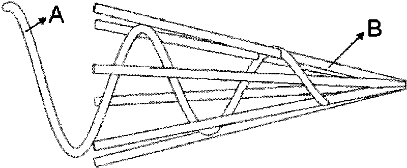
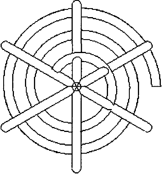
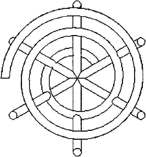
[0011] Such as figure 1 As shown: the patent of the invention consists of a helical structure swirl guide and a conventional filter screen. The cross section of the helical structure is circular and the diameter is less than 2 mm. The pitch of the helical introducer is 5-20 mm.
Login to View More PUM
| Property | Measurement | Unit |
|---|---|---|
| Pitch | aaaaa | aaaaa |
Abstract
The invention discloses a vena cava filter with a swirling guider, aiming at solving the problem of thrombus blockage after the traditional filter is implemented in the vena cava. The vena cava filter with the swirling guider consists of two parts, namely a swirling guider part and a normal umbrella-shaped filter screen, and the two parts are combined into a whole. The swirl guider is characterized in that spiral distances in a spiral structure which is from small to big along the opening direction of the filter screen ranges from 5 to 20 millimeters, and the section of a spiral metal wire takes the shape of a circle with the diameter less than 2 millimeters. The swirl guider of the filter has the function of enabling blood stream in the filter to move rotatably, and simultaneously increases the flowing shear stress, better scours the filter screen and reduces or eliminates the accumulation of thrombus in the filter, thereby achieving the purpose of preventing or alleviating filter blockage caused by thrombus and having important clinical application value.
Description
technical field [0001] The invention relates to a medical device, more specifically, a vena cava filter that guides the blood flow to rotate and flow forward. Background technique [0002] The inferior vena cava filter is an interventional device used to prevent the thrombus formed in the deep vein of the patient's lower extremity from flowing into the heart. After an inferior vena cava filter is implanted, blood clots often block the filter, forcing the doctor to remove the filter and reinsert a new filter. The current vena cava filter has been developed to the second generation. Although the second-generation vena cava filter can be sent into the human body with a catheter, it can also be removed from the human body with a catheter, but the problem of thrombus reocclusion after implantation of the vena cava filter has not been solved. The study found that the human aortic arch is in a three-dimensional spiral shape, and it is this spiral structure that makes the blood fl...
Claims
Login to View More Application Information
Patent Timeline
 IPC IPC(8): A61F2/01
Inventor陈颖邓小燕樊瑜波
OwnerBEIHANG UNIV