Particulate matter detection sensor

a technology of particle matter and detection sensor, which is applied in the direction of measurement devices, instruments, scientific instruments, etc., can solve the problems of increased pressure loss of dpf, clogging of pores, and difficulty in executing the correct introduction of exhaust gas containing pm to the detection element without using an additional member, and achieves stable sensor and high accuracy

Inactive Publication Date: 2012-05-03
DENSO CORP
View PDF1 Cites 24 Cited by
  • Summary
  • Abstract
  • Description
  • Claims
  • Application Information

AI Technical Summary

Benefits of technology

[0020]It is therefore desired to provide a particulate matter detection sensor equipped with a particulate matter detection element having a stable dead time period with high reliability, capable of detecting a quantity of particulate matter contained in a target detection gas on the basis of electrical characteristics of an area between a pair of detection electrodes formed on a detection part in the particulate matter detection element with a simple structure. The electrical characteristics of the area between the pair of the detection electrodes are changed on the basis of the quantity of particulate matter accumulated on the area between the pair of detection electrodes with a simple configuration.
[0022]When particulate matter contained in the target detection gas is introduced onto the detection part, the structure of the particulate matter detection sensor according to the exemplary embodiment prevents the target detection gas from reaching the area having non-uniform electric field intensity between the detection electrodes at the outside of the projected area of the target detection gas introduction hole, and makes it possible to supply the target detection gas onto the area having the uniform electric field intensity between the detection electrode on the detection part. This structure makes it possible to suppress and avoid particulate matter from being locally accumulated on the area having non-uniform electric field intensity between the detection electrodes, and to prolong the necessary period of time to execute a process of regenerating the particulate matter detection sensor because of obtaining a stable dead time period and avoiding an excess accumulation of particulate matter on the detection part.
[0024]According to the exemplary embodiment, because the target detection gas introduction hole is open to the inside area having the uniform electric field intensity generated in the detection part. The target detection gas is introduced through the target detection gas introduction hole directly to the detection part. Particulate matter contained in the introduced target detection gas is accumulated only on the area having the uniform electric field intensity. This structure makes it possible to suppress and avoid particulate matter from being locally accumulated on the area having non-uniform electric field intensity. This makes it possible to avoid a conductive path from being made on the detection part by the locally accumulated particulate matter, and to avoid undetectable state of the particulate matter detection sensor, and to suppress incorrect operation of the particulate matter detection sensor.
[0026]According to the present exemplary embodiment, because the target detection gas is introduced onto the area having the uniform electric field intensity within the inside of the straight line part of the detection electrodes formed in parallel on the heat resistance substrate. This makes it possible to provide the particulate matter detection sensor capable of outputting stable sensor output with high accuracy.

Problems solved by technology

When a quantity of PM captured in the pores formed in the partition walls in the DPF is increased, the pores are clogged and a pressure loss of the DPF is thereby increased.
By the way, the technique disclosed in the conventional patent document 2 previously described has a complicated gas-flowing path and makes it difficult to execute correct introduction of exhaust gas containing PM to the detection element without using an additional member.
Using the additional member causes a complicated sensor structure and increases the manufacturing cost of the detection device.
Further, such a complicated structure of the gas-flowing path causes a problem of accumulating PM on the area other than the detection part in which the detection electrodes are formed.
There is a possibility of it being difficult to rapidly detect a quantity of PM contained in the target detection gas with high accuracy.
This causes non-uniform electric field generated between the detection electrodes.
When non-uniform electric field intensity is generated, it is difficult to have a constant PM accumulation speed, and the PM accumulation speed is fluctuated during a dead time period.
This increases the difference in quantity of accumulated PM between the areas having the different electric field intensity, and increases the fluctuation of the dead time period.
This decreases the reliability of the PM sensor.

Method used


Image

  • Particulate matter detection sensor
  • Particulate matter detection sensor
  • Particulate matter detection sensor

Examples


first embodiment

[0051]A description will be given of a particulate matter detection sensor 1 (hereinafter, referred to as the “PM detection sensor 1”) according to a first exemplary embodiment of the present invention with reference to FIG. 1A to FIG. 8B.

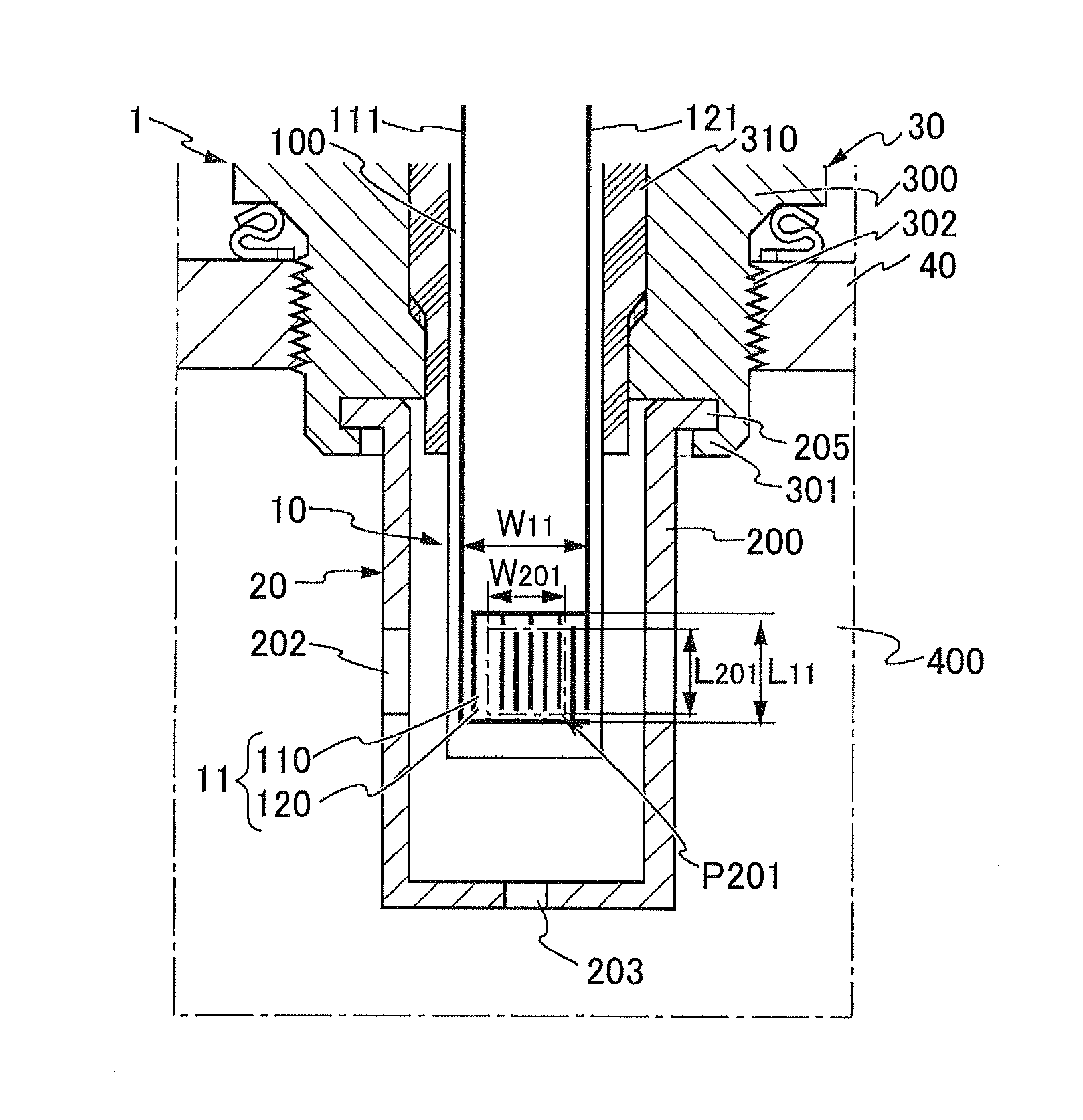
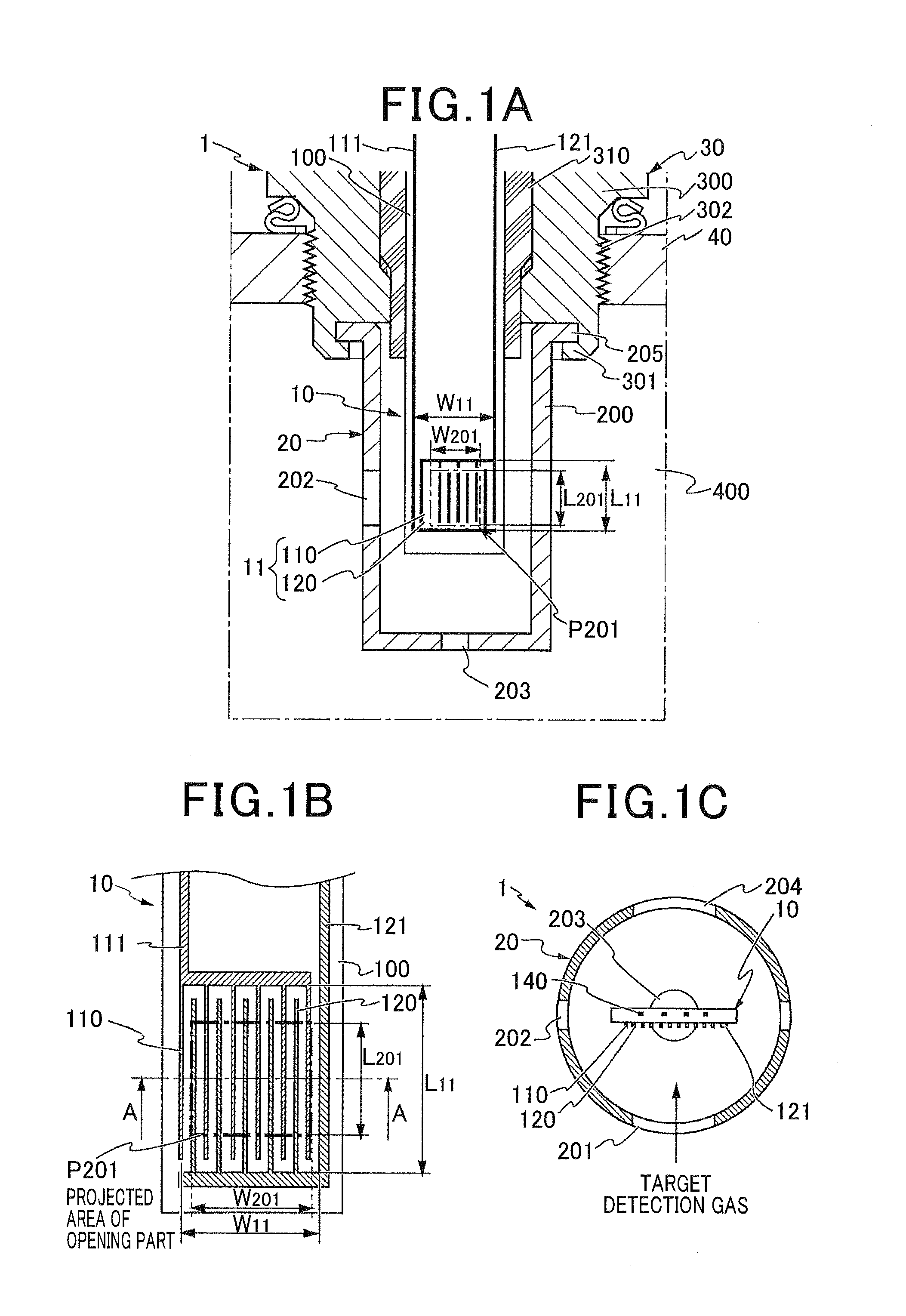
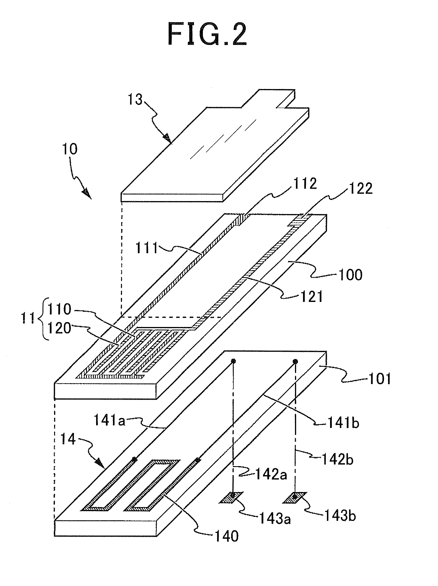
[0052]FIG. 1A is a view showing a schematic cross section of a main part of the PM detection sensor 1 according to the first exemplary embodiment. FIG. 1B is a view showing a schematic cross section of a part of the PM detection sensor 1 according to the first exemplary embodiment. FIG. 1C is a view showing a cross section of the PM detection sensor 1 along the A-A line shown in FIG. 1B. FIG. 2 is a development view showing a perspective structure of a PM detection element 10 in the PM detection sensor 1 according to the first exemplary embodiment.

[0053]The PM detection sensor according to the first exemplary embodiment can be applied to exhaust gas purifying systems for internal combustion engines. The PM detection sensor detects electrical charac...

second exemplary embodiment

[0108]A description will now be given of a PM detection sensor 1b according to the second exemplary embodiment of the present invention with reference to FIG. 9.

[0109]FIG. 9 is a development view showing a perspective structure of a detection element 10b in the PM detection sensor 1b according to the second exemplary embodiment of the present invention.

[0110]Each of the PM detection sensor 1 according to the first exemplary embodiment and the PM detection sensor 1a as the modification has the detection part 11 (11a) composed of the detection electrodes 110 (110a) and 120 (120a) arranged in a comb structure.

[0111]On the other hand, the PM detection sensor 1b according to the second exemplary embodiment has the detection par 11b in which a pair of detection electrodes 110b and 120b is formed at a predetermined constant interval in parallel on the heat resistant substrate 100 along the longitudinal direction of the heat resistant substrate 100. In the PM detection sensor 1b, the detect...

third exemplary embodiment

[0121]A description will now be given of a PM detection sensor 1c according to the third exemplary embodiment of the present invention with reference to FIG. 11A, FIG. 11B, FIG. 12A1, FIG. 12A2, FIG. 12B1, FIG. 12B2, FIG. 12C1 and FIG. 12C2.

[0122]FIG. 11A is an expanded view showing the PM detection element 10c of the PM detection sensor 1c according to the third exemplary embodiment of the present invention. FIG. 11B is a view showing a cross section of the detection element 10c of the PM detection sensor 1c according to the third exemplary embodiment. FIG. 12A1, FIG. 12B1 and FIG. 12C1 are views showing a schematic cross section of the PM detection sensor 1c according to the third exemplary embodiment and the effect of the PM detection sensor 1c. FIG. 12A2, FIG. 12B2 and FIG. 12C2 are views showing a schematic side surface of the PM detection sensor 1c according to the third exemplary embodiment and the effect of the PM detection sensor 1c.

[0123]In the first and second embodiment...


PUM


Abstract

In a PM detection sensor, a gas introduction hole is formed in a cover unit which surrounds a PM detection element. The gas introduction hole faces a detection part having detection electrodes of a comb structure. A projected part generated when an opening part of the gas introduction hole is projected on the detection part is within an inside area of the detection part. The projected area of the opening part of the gas introduction hole is positioned within the inside area having a uniform electric field intensity between the detection electrodes. The target detection gas is directly introduced through the gas introduction hole to the area having the uniform electric field intensity generated on the detection part. PM contained in the target detection gas is captured and accumulated on the area having the uniform electric field intensity but not on the area having non-uniform electric field intensity.

Description

CROSS-REFERENCE TO RELATED APPLICATION[0001]This application is related to and claims priority from Japanese Patent Application No. 2010-242138 filed on Oct. 28, 2010, the contents of which are hereby incorporated by reference.BACKGROUND OF THE INVENTION[0002]1. Field of the Invention[0003]The present invention relates to particulate matter detection sensors mounted to an exhaust gas purifying system for an internal combustion engine of a motor vehicle, and are capable of detecting particulate matter contained in target detection gas such as exhaust gas emitted from the internal combustion engine.[0004]2. Description of the Related Art[0005]In general, a diesel engine, for example, mounted to a motor vehicle, is equipped with a diesel particulate filter (hereinafter, referred to as the “DPF”). Such a DPF captures particulate matters (hereinafter, referred to as the “PM” for short) as environmental pollution matter contained in exhaust gas emitted from the diesel engine. The PM conta...

Claims


Application Information

Patent Timeline
Patent Type & Authority Applications(United States)
IPC IPC(8): G01M15/10
CPCG01N15/0656
Inventor KIMATA, TAKEHITOWATARAI, TAKEHIRO
Owner DENSO CORP
Why Eureka
Try Eureka