Device for adjusting and positioning horizontal offset for working rollers of rolling mill

A technology for adjusting positioning and working rolls, which is applied in the direction of metal rolling stands, metal rolling mill stands, metal rolling, etc., can solve the problems of large working rolls and cannot meet the requirements of thin-gauge strip steel rolling, and achieve the elimination of Clearance, high stability effect

Active Publication Date: 2012-04-25
CERI TECH
View PDF6 Cites 1 Cited by
  • Summary
  • Abstract
  • Description
  • Claims
  • Application Information

AI Technical Summary

Problems solved by technology

[0006] At present, four-high and six-high cold rolling mills are widely used in the field of strip steel production, but because the work rolls have no lateral support rolls, that is, there is no additional roll system to bear the horizontal force of the work rolls, so the size of the work rolls is relatively large. Reducing the diameter of the work roll is limited by the horizontal force of the work roll, which cannot meet the rolling requirements of thin-gauge strip steel

Method used


Image

  • Device for adjusting and positioning horizontal offset for working rollers of rolling mill
  • Device for adjusting and positioning horizontal offset for working rollers of rolling mill
  • Device for adjusting and positioning horizontal offset for working rollers of rolling mill

Examples


Embodiment Construction

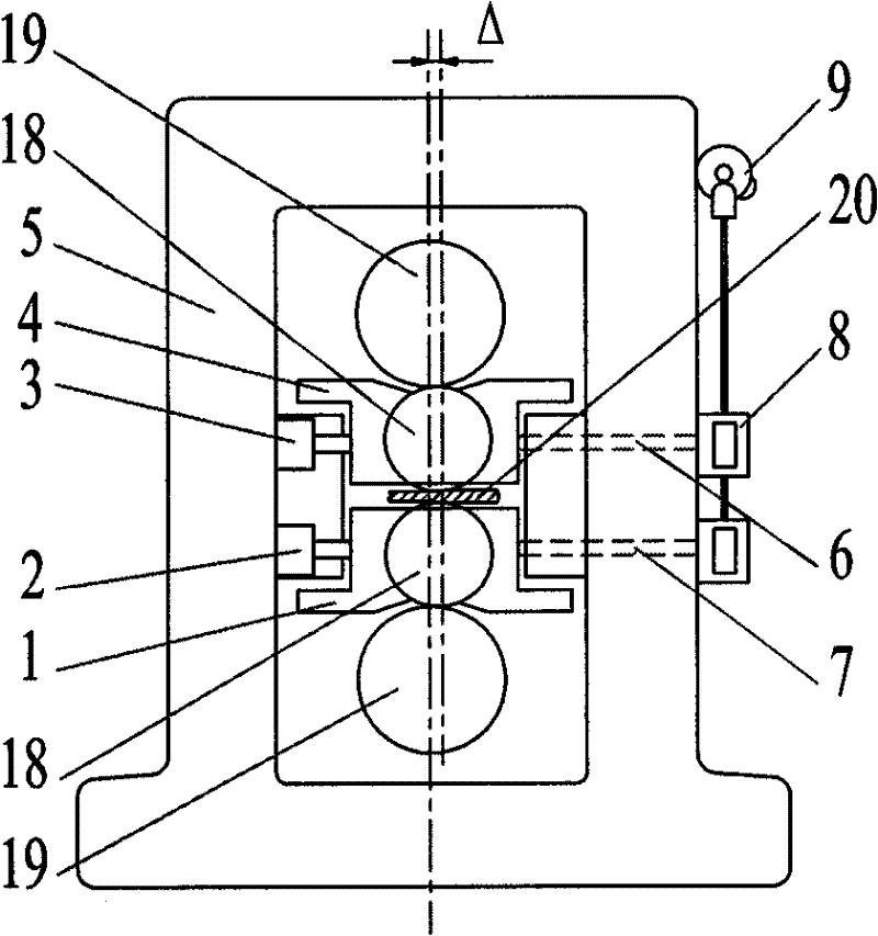
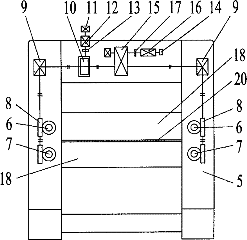
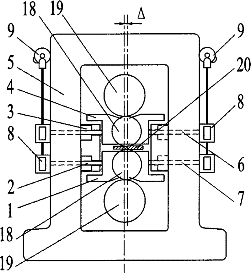
[0026] see figure 1 , figure 2 with Figure 4 , the positioning device for adjusting the horizontal offset of the work rolls of the rolling mill according to the present invention. Among them: including the position control mechanism installed on the column on the entrance side of the rolling mill frame 5 and opposite to the bearing housings 4 and 1 at both ends of the upper and lower work rolls of the rolling mill, and the position control mechanism installed on the column on the exit side of the rolling mill, and the position The relative compression balance mechanism of the control mechanism. The position control mechanism includes an upper push rod 6 and a lower push rod 7. The upper and lower push rods 6, 7 pass through the column, and one end is against one side of the upper and lower work roll bearing housings 4, 1, and the other end is connected to the upper and lower work roll bearing housings 4, 1. The worm screw propeller 8 of the push rod transmission mechanism...


PUM


Abstract

The invention discloses a device for adjusting and positioning horizontal offset for working rollers of a rolling mill, which comprises a position control mechanism which is arranged on an upright post on an entrance side of a frame (5) of the rolling mill and arranged opposite to bearing seats (4, 1) at two ends of an upper working roller and a lower working roller, and a pressure balance mechanism which is arranged on an upright post on an exit side of the frame of the rolling mill and is opposite to the position control mechanism. The position control mechanism comprises an upper push rod (6) and a lower push rod (7) which pass through the upright post. One end of each of the upper push rod (6) and the lower push rod (7) is propped against one side of each of the bearing seats of the upper working roller and the lower working roller, while the other end is connected with a push rod transmission mechanism. The pressure balance mechanism comprises an upper balance hydraulic cylinder (3) and a lower balance hydraulic cylinder (2). The device is applied to a four-roller or a six-roller cold-rolling mill or a reversing cold mill of which the working rollers have no side supports. The working rollers can be horizontally moved correspondingly according to rolling parameters. The horizontal offset of the working rollers is adjusted and positioned, so that the horizontal force thereof is reduced, and the working rollers smaller than the conventional design are realized and roll strip steel in thin specification.

Description

technical field [0001] The invention relates to a device for adjusting and positioning work rolls of a rolling mill, in particular to a device for adjusting and positioning the horizontal offset of work rolls of a four-high and six-high cold rolling mill. Background technique [0002] Commonly used cold strip mills have four-high, six-high, twelve-high, eighteen-high and twenty-high structural forms. The minimum thickness of the rolled strip is related to the diameter of the work roll. When the material of the roll is steel, the empirical formula is: [0003] h min ≈(1 / 1500~1 / 2000)D w ; [0004] where: h min is the minimum thickness of the strip; D w is the work roll diameter. [0005] In order to roll thin gauge strip, it is necessary to use small diameter work rolls. For four-high and six-high cold rolling mills, during the rolling process, the strip steel and the back-up roll or intermediate roll exert a horizontal force on the work roll body, which is transmitted ...

Claims


Application Information

Patent Timeline
Patent Type & Authority Patents(China)
IPC IPC(8): B21B31/32
Inventor 陈南宁李龙男沈志前武其俭江东海
Owner CERI TECH
Why Eureka
Try Eureka