Supercharge Your Innovation With Domain-Expert AI Agents!

Metal carrier u-shaped core forming device

A metal carrier and core technology, applied in the field of metal carrier U-shaped core forming devices, can solve the problems of high labor intensity, low production efficiency and high production cost, and achieve simple and compact structure, high production efficiency and low manufacturing cost Effect

Active Publication Date: 2011-12-21
WUXI SHENGHE TECH
View PDF0 Cites 0 Cited by
  • Summary
  • Abstract
  • Description
  • Claims
  • Application Information

AI Technical Summary

Problems solved by technology

The metal carrier is composed of a shell and a core body. In the prior art, the core body is made of metal corrugated plates and flat plates that are stacked and rolled up. Most of the production of the core body is semi-mechanized and semi-manual. The production process is complex and the production efficiency is high. Low, the labor intensity of workers is high, and the production cost is also high
In addition, whether the rolled metal carrier core is single-core, double-core or triple-core, a mandrel must be used. Since the mandrel must have a certain strength, the diameter of the mandrel cannot be small. When the mesh number of the metal carrier When it is relatively large (small filter hole), the hole produced by the mandrel is obviously larger than the filter hole, which will reduce the filtering effect
The applicant has invented the metal carrier (such as Figure 7 As shown, wherein 1' is the shell, 2' is the U-shaped core body, which is composed of multi-layer U-shaped flat plates and U-shaped corrugated plates alternately stacked), there is no U-shaped core body 2' that can be used in the prior art. equipment

Method used


Image

  • Metal carrier u-shaped core forming device
  • Metal carrier u-shaped core forming device
  • Metal carrier u-shaped core forming device

Examples


Embodiment Construction

[0029] The specific implementation manners of the present invention will be further described in detail below in conjunction with the accompanying drawings.

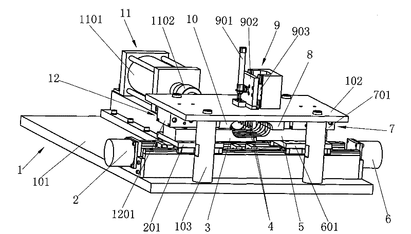
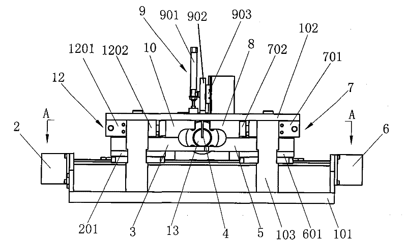
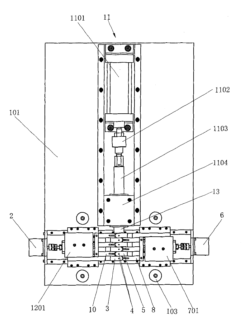
[0030] Such as figure 1 As shown in ˜5, the present invention includes a frame 1, and the frame 1 is formed by connecting a bottom plate 101 and a top plate 102 through four pillars 103. The lower left propulsion mechanism 2 and the lower right propulsion mechanism 6 are installed on the base plate 101, and the lower left propulsion mechanism 2 is the same as the lower right propulsion mechanism 6, both of which are single-axis drivers; The screw nut and the driving motor are composed of linear guide rails and screw nuts respectively connected to the left slider 201 and the right slider 601, and the left lower forming block 3 and the right lower forming block 5 are respectively installed on the left slider 201 and the right sliding block 601 , the lower left propelling mechanism 2 and the lower right propelling mechani...


PUM


Abstract

The invention relates to a metal carrier U-shaped core body forming device, which is characterized in that the lower left forming block and the lower right forming block are respectively connected with the lower left propulsion mechanism and the lower right propulsion mechanism, and the lower left forming block and the lower right forming block are respectively provided with four points. A round forming cylindrical surface, the front ends of which are respectively provided with sliding teeth and sliding grooves for mutual sliding sleeves; the upper left forming block and the upper right forming block are connected to the upper left propulsion mechanism and the upper right propelling mechanism respectively, and the upper left forming block and the upper right forming block are respectively provided with There is a quarter-circle forming cylindrical surface, the front end of which is respectively provided with upper sliding teeth and upper chute for sliding sleeves; multiple thimbles are connected to the pressing mechanism, when the left lower forming block, right lower forming block, left upper forming block and When the upper right forming block is closed, it forms a forming cylinder whose diameter is the same as that of the processed core. The invention has simple and compact structure, low manufacturing cost, high production efficiency and low labor intensity when used for forming metal carrier U-shaped core bodies.

Description

technical field [0001] The invention relates to a special processing equipment, in particular to a metal carrier U-shaped core body forming device for an exhaust gas purifier. Background technique [0002] The exhaust gas purifier is installed in the exhaust pipe, which can effectively control the pollution emitted by the vehicle. Catalyst supports for exhaust gas purifiers mainly include honeycomb ceramic supports and metal supports. At present, most exhaust gas purifiers use honeycomb ceramic carriers, but compared with honeycomb ceramic carriers, metal carriers have the advantages of thinner walls, higher opening ratio, and higher thermal conductivity. It can reduce the exhaust resistance of automobiles, improve the dynamic performance of engines, and improve exhaust Purification efficiency, but also prolong the service life of the exhaust gas purifier. With the improvement of national emission standards for automobiles, metal carriers have been more widely used. The m...

Claims


Application Information

Patent Timeline
Patent Type & Authority Patents(China)
IPC IPC(8): B21C23/00
Inventor 吴昌文
Owner WUXI SHENGHE TECH
Features
  • R&D
  • Intellectual Property
  • Life Sciences
  • Materials
  • Tech Scout
  • Unparalleled Data Quality
  • Higher Quality Content
  • 60% Fewer Hallucinations
Learn More