Technique and device for processing shaft type and pipe type workpieces in tightened state

A processing technology and workpiece technology, which is applied in the processing technology field of shaft and tube workpieces, can solve the problems of unrealistic processing of workpieces and technical difficulties, and achieve enhanced rigidity, improved machining accuracy, and reduced radial runout and roundness Waiting for the effect

Inactive Publication Date: 2010-06-16
赵显华
View PDF1 Cites 16 Cited by
  • Summary
  • Abstract
  • Description
  • Claims
  • Application Information

AI Technical Summary

Problems solved by technology

The floating chuck can clamp the workpiece while accurately positioning it, but it needs to be pulled by the middle tie rod, so it cannot realize the processing of the workpiece under tension
[0007] Combining the existing technologies, it is the key to improve the machining acc

Method used


Image

  • Technique and device for processing shaft type and pipe type workpieces in tightened state
  • Technique and device for processing shaft type and pipe type workpieces in tightened state
  • Technique and device for processing shaft type and pipe type workpieces in tightened state

Examples


Embodiment 1

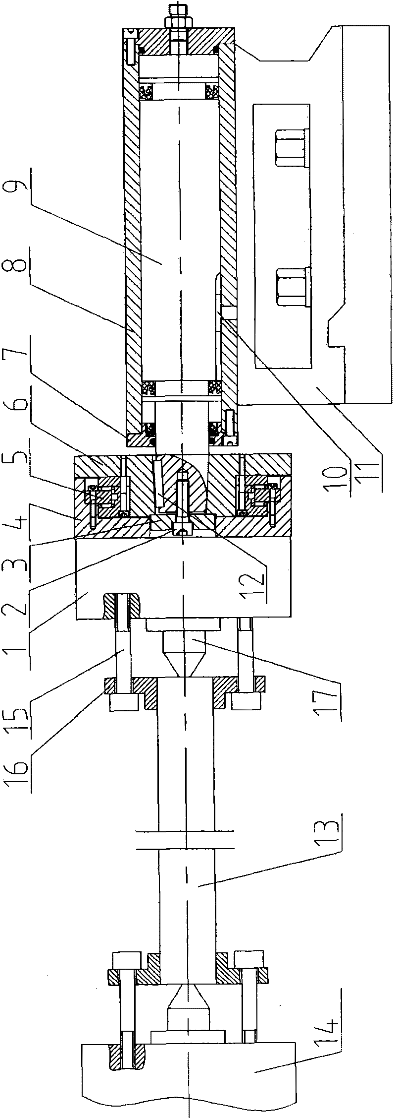
[0023] Such as figure 1 As shown, a process head 16 is installed at both ends of the shaft workpiece 13. The process head 16 is in the shape of a disc and can be fixed with the shaft workpiece 13 through threads or other forms. Connect the front end process head and the front connecting plate 14 together by bolts 15, and connect the back end process head and the rear connecting plate 1 together. Both connecting plates are equipped with centers 17, and the process head is connected to the connecting plate at the same time. 17 to withstand the center holes at both ends of the shaft workpiece 13. The axis of the center 17 is on the same straight line. The front end connecting plate 14 is installed at the end of the machine tool spindle in the same manner as the chuck at the end of the spindle. In this way, the front process head and the machine tool spindle are pulled by the connection with the front connecting plate 14. Connect the rear connecting plate 1 with a tensioning devi...

Embodiment 2

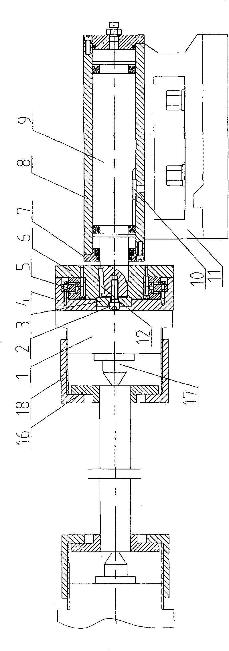
[0028] The difference between this embodiment and embodiment 1 is that the connection method of the process head and the connecting plate adopts such as figure 2 In the form shown, a connecting sleeve 18 is fitted on the process head, the connecting sleeve 18 is provided with internal threads, and the outer side of the connecting disk is provided with external threads. The connecting sleeve 18 is moved to the end surface of the connecting disk and rotated until it is tightened. The machine tool spindle drives the workpiece to rotate through the front connecting plate 14, the connecting sleeve 18 and the process head.

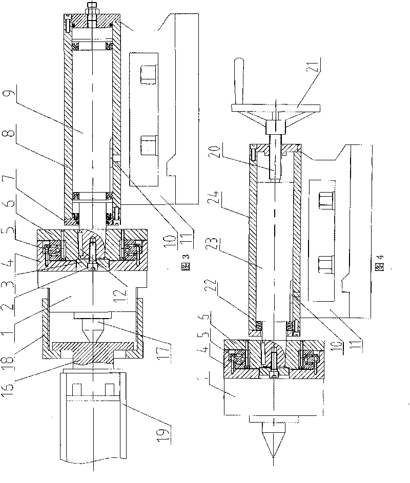
[0029] The process of processing tube workpiece 19 is as image 3 As shown, the difference from the machining of the shaft-like workpiece 13 lies in the structure of the process head used. One end of the process head used extends into the inner hole of the pipe-like workpiece 19, and the two are fixedly connected by supporting the workpiece.

Embodiment 3

[0031] The tensioning device of this embodiment is different from the tensioning device of embodiment 1. Figure 4 The spiral moving mechanism shown includes a sleeve 24, a tie rod 23, a screw 20, a bearing seat 6, a bearing 5, a disc seat 4, and a base 11. The sleeve 24 is installed on the base 11, and the bottom structure of the base 11 and the lathe tail The way of moving and fixing on the machine tool is the same as that of the tailstock of the lathe on the lathe. The sleeve 24 is provided with a pull rod 23. One end of the pull rod 23 extends out of the front end cover of the sleeve 24. The rear end cover of the sleeve 24 is screwed with a screw 20. The front end of the screw 20 is pressed against the back end of the pull rod 23. A handwheel 21 is installed at the rear end of the A spring 22 is provided between the pull rod 18 in the sleeve 24 and the front end cover of the sleeve 24. A bearing seat 6 is installed at one end of the pull rod 23 protruding from the sleeve 2...


PUM


Abstract

The invention provides a technique and a device for processing shaft type and pipe type workpieces in a tightened state. In the technique, the two ends of a workpiece are positioned by propping a central hole by a tip; then one end of the workpiece at a machine tool spindle end is pulled or a technical head of the workpiece at the machine tool spindle end is pulled; the tip at a back end and the other end of the workpiece or the technical head at the other end are pulled backwards under the same pulling force so as to ensure that the workpiece is in the tightened state; and therefore, the workpiece is not only positioned through the tip, but also is in the tightened state to perform outer circle processing. The device comprises a floating chuck arranged at the front end of a machine tool spindle and a tightening device arranged on the tail part of a machine tool, wherein the tightening device is also provided with the floating chuck; and the back end of the tightening device is provided with a hydraulic cylinder for a pull rod of the floating chuck. The technique and the device can ensure that the same positioning datum is adopted during multi-station processing and process the workpiece in the tightened state, so the processing rigidity of the workpiece is enhanced, the workpiece tends to elongate in the axial direction and the processing accuracy can be effectively improved.

Description

Technical field [0001] The invention relates to a processing technology for shaft and tube workpieces, and belongs to the technical field of outer surface processing of shaft and tube workpieces. Background technique [0002] At present, when machining slender shaft and tube parts on a lathe, one clamp and one top are usually used, that is, one end of the lathe head is clamped by a chuck, and one end of the tailstock is clamped by the top. This processing method is tightened. When the tightening force is not well controlled, if the force is too large, it will easily bend the workpiece. If the force is too small, the workpiece will be inaccurately positioned in the radial direction. In addition, due to the increase in temperature during the processing, the workpiece cannot be stretched and bends. , And the dimensional tolerance and shape tolerance of the workpiece after processing are not easy to guarantee. [0003] Chinese patent document CN201186355 discloses a "tooling and fixtu...

Claims


Application Information

Patent Timeline
IPC IPC(8): B23Q3/00B23B13/02
Inventor 王爱福赵显华
Owner 赵显华
Why Eureka
Try Eureka