Roller blind piece

A technology of rolling shutters and curtains, which is applied in door/window protection devices, shutters/movable grilles, windows/doors, etc., and can solve the problems of inconvenient production, construction, installation and maintenance, and the lack of modularization of rolling shutters. Wind resistance performance can not be guaranteed and other problems, to achieve the effect of improving wind resistance performance, smooth retractable operation, and low friction

Active Publication Date: 2010-06-16
WUXI JIEYANG ENERGY SAVING TECH
View PDF0 Cites 7 Cited by
  • Summary
  • Abstract
  • Description
  • Claims
  • Application Information

AI Technical Summary

Problems solved by technology

[0003] The main part of the door body or form of a rolling door or a rolling window is a rolling shutter sheet. The following defects generally exist in the structure of the traditional rolling shutter sheet: (1), the rolling shutter sheet is not fully modularized, It brings a lot of inconvenience to production, construction, installation and maintenance; (2), when rolling or unwinding the roller blind, the friction between the curtains is large, which makes the noise loud; (3), rolling The main structure of the curtain sheet is made of metal material, which has poor thermal insulation performance when ensuring the high strength of the roller blind sheet; (4), the sides of the roller blind sheet are smooth and flat, and the curtain itself The bending resistance is poor, and the wind resistance performance cannot be guaranteed during use, and the blinds are prone to mutual extrusion and deformation; It is easy to get stuck in the guide rail when rolling or unwinding, and the side buckle is made of plastic, which has a short service life

Method used


Image

  • Roller blind piece
  • Roller blind piece
  • Roller blind piece

Examples


Embodiment Construction

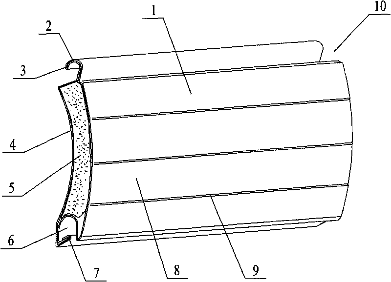
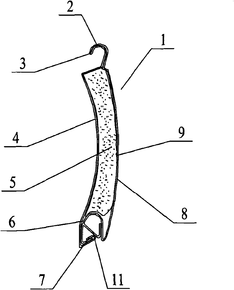
[0013] As shown in the figure, the present invention includes a curtain body 1, the curtain body 1 protrudes upwards with an upper hook 2, and the lower part is recessed to form a lower hook 6, and the upper hook 2 can be buckled with the lower hook 6 of the adjacent curtain The upper hook 2 and the lower hook 6 are a large circular arc structure that cooperates with each other. The large circular arc structure can increase the contact area of ​​the connection between the curtains, so that when rolling or unwinding, the distance between the curtains Small friction and low noise; in order to make the curtain more compact when rolling up, run smoothly, reduce friction, avoid extrusion and deformation between the curtains, and run without impact, the upper hook 2, the lower hook 6 and the curtain body 1 The concave arc surface 4 is located on the same arc surface.

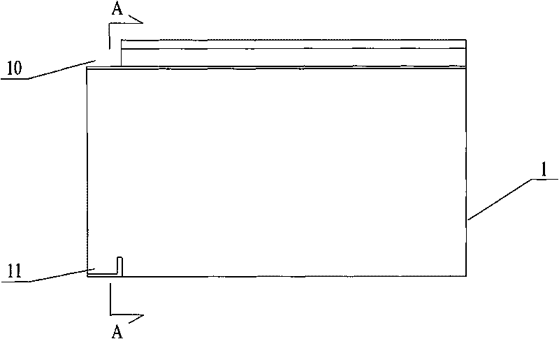
[0014] Such as image 3 As shown, one end of the upper hook 2 on the curtain body 1 is provided with a notch 10, a...


PUM


Abstract

The invention relates to a roller blind piece applied to roller blind doors or windows. The roller blind piece comprises a piece body. An upper hook is formed through upward convex extension of the piece body and a lower hook is formed through depression of the lower part of the piece body. The upper hook can be connected with the adjacent lower hook of the piece body by buckling. The roller blind piece is characterized in that one end of the upper hook on the piece body is provided with a nick and the lower hook is provided with a retaining groove corresponding to the nick; the nick and the retaining groove are arranged at the same end of the same piece body; and when the upper hook on one roller blind piece is connected with the lower hook on the other roller blind piece by buckling, one end of the upper hook, which is provided with the nick, is blocked by the retaining groove. The roller blind piece has compact and reasonable structure, small friction when rolling or unrolling and low noise, is smooth in rolling and unrolling operations and safe and reliable in connection, and simultaneously has good compression strength, anti-bending property, anti-torsion strength and thermal insulation property.

Description

technical field [0001] The invention relates to a rolling shutter structure, in particular to a rolling shutter applied to a rolling door or a rolling window. Background technique [0002] The rolling shutter door is a kind of door that is connected in series with multi-joint movable doors, and in a fixed slideway, the door is rotated up and down centered on the scroll above the door. Rolling shutter doors are suitable for commercial facades, garages, shopping malls, hospitals, factories and mines and other public places or residences. It is especially suitable for some occasions where the door opening is large and it is inconvenient to install the ground door body, such as garage doors, fireproof shutter doors of shopping malls, hangar doors, etc. The shutter door can be opened conveniently and quickly. [0003] The main part of the door body or form of a rolling door or a rolling window is a rolling shutter sheet. The following defects generally exist in the structure of ...

Claims


Application Information

Patent Timeline
Patent Type & Authority Applications(China)
IPC IPC(8): E06B9/08E06B9/84E06B5/16
Inventor 顾国东
Owner WUXI JIEYANG ENERGY SAVING TECH
Why Eureka
Try Eureka