Hydraulic butterfly valve with automatic lubricating device

An automatic lubrication and butterfly valve technology, applied in the direction of valve device, valve operation/release device, valve lift, etc., can solve the problems of rotating shaft locking, switch failure, etc., and achieve the effect of ensuring safe production and improving service life

Inactive Publication Date: 2010-06-16
铜陵市永生机电制造有限责任公司
View PDF0 Cites 0 Cited by
  • Summary
  • Abstract
  • Description
  • Claims
  • Application Information

AI Technical Summary

Problems solved by technology

However, during use, if the conveying medium contains water and dust, water and fine dust will often seep into the space between the rotating shaft and the bearing sleeve, resulting in the gradual locking of the rotating shaft and the failure of the switch, which seriously affects the safety of production. as a result of

Method used


Image

  • Hydraulic butterfly valve with automatic lubricating device
  • Hydraulic butterfly valve with automatic lubricating device

Examples


Embodiment Construction

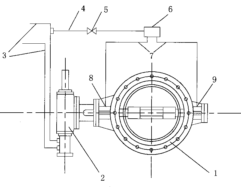
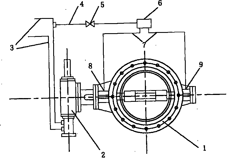
[0008] The present invention will be further described below in conjunction with embodiment (accompanying drawing):

[0009] As shown in Figure 1, 1 is a common butterfly valve. It is usually composed of a valve housing, a rotating shaft and a butterfly plate fixed on the rotating shaft. Its seals are divided into elastic seals and metal seals. body, or attached to the periphery of the butterfly plate. The 2nd, hydraulic drive system, it comprises oil cylinder, piston, gear rod that is connected on the piston, the gear that is connected with butterfly valve rotating shaft, and the hydraulic oil pipe 3 that feeds oil to oil cylinder is made up of. The 4th, branch circuit oil pipe, its one end is connected hydraulic oil pipe 3, and one end is connected with oil distribution joint 6, and a valve 5 is installed in the middle, to control branch circuit oil supply oil supply or not. The 7th, pressure-measuring flexible pipe, altogether two, their one end connects the oil distributi...


PUM


Abstract

The invention discloses a hydraulic butterfly valve with an automatic lubricating device, comprising a butterfly valve, a hydraulic driving system, oil feed holes, a branch lubricating oil pipe, a valve, an oil path distribution joint and a pressure measuring flexible pipe, wherein the branch lubricating oil pipe, the valve, the oil path distribution joint and the pressure measuring flexible pipe are connected with the oil feed holes and the hydraulic oil pipe. The oil feed holes are positioned on an upper bearing sleeve and a lower bearing sleeve of a rotating shaft of the butterfly valve and are welded with oil pipe joints; when the valve on the branch lubricating oil pipe is opened, pressure oil enters into the pressure measuring flexible pipe from the oil pipe path distribution joint along the branch oil pipe and then enters into the upper bearing sleeve and the lower bearing sleeve of the rotating shaft of the butterfly vale from the oil feed holes, thereby achieving the purpose of lubricating bearings. The hydraulic butterfly valve with the automatic lubricating device can achieve the effect of automatically lubricating rotating bearings of the hydraulic butterfly valve so as to avoid the problem of gradual lock braking caused by the seepage of water and the entrance of fine dust into the hydraulic butterfly valve, improve the integral performance of the valve and prolong the service life of the valve.

Description

technical field [0001] The invention relates to a hydraulic butterfly valve, in particular to a hydraulic butterfly valve with an automatic lubricating device. Background technique [0002] The hydraulic butterfly valve in the prior art is mainly composed of a valve body, a valve stem, a butterfly plate and an oil pressure drive system for driving the valve stem to rotate. The butterfly plate can be fixed on the valve stem in various ways and placed in the valve cavity. The valve stem passes through the valve body through the diameter of the circular section of the valve cavity, and one end is adapted to the hydraulic drive device outside the valve body. The hydraulic drive system is mainly composed of an oil cylinder, a piston, a rack and a gear, and a pressure oil pipe connected to the oil cylinder. The hydraulic butterfly valve has the characteristics of simple structure, small size, light weight, low material consumption, small installation size, rapid switching, 90° re...

Claims


Application Information

Patent Timeline
IPC IPC(8): F16K1/22F16K1/32F16K31/163
Inventor 朱俊生
Owner 铜陵市永生机电制造有限责任公司
Why Eureka
Try Eureka