Magnetic image sensor

A technology of image sensor and sensor, applied in the field of magnetic image sensor

Inactive Publication Date: 2010-06-16
XIANGTAN UNIV +1
View PDF2 Cites 5 Cited by
  • Summary
  • Abstract
  • Description
  • Claims
  • Application Information

AI Technical Summary

Problems solved by technology

[0002] The existing magnetic sensor is mainly aimed at the measurement of the point magnetic field (single element probe) and the measurement of the average magnetic field strength in the area (coil method). For the distribution of the magnetic field in a certain area, especially for the complex alternating dynamics in the area Magnetic field, in addition to a certain theoretical analysis, so far there is no experimental measurement method, the present invention has successfully realized the real-time data acquisition of the complex alternating dynamic magnetic field - magnetic image in a certain plane area, and can reproduce it on the computer The dynamic evolution diagram of the magnetic field provides a new method for analyzing the faults of electrical appliances and electronic products, eliminating interference and improving the design through magnetic images; for finding defects in mechanical parts and improving the shape; for multidisciplinary research on certain physical properties of new materials. The research methods are the cutting-edge research results in this field

Method used


Image

  • Magnetic image sensor
  • Magnetic image sensor
  • Magnetic image sensor

Examples


Embodiment

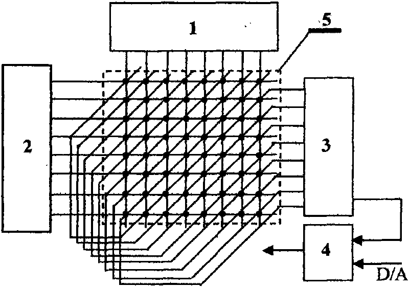
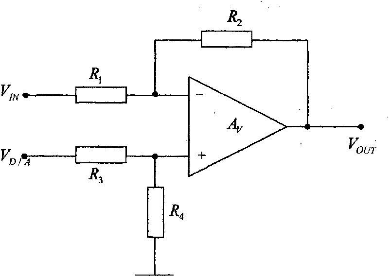
[0010] Now make a magnetic image sensor, its structure is as attached figure 1 As shown in the figure, (1) is an eight-to-one multi-way switch for column power supply, (2) is an eight-to-one multi-way switch for row power supply, (3) is an eight-to-one multi-way switch for output, and all three multi-way switches are selected DG408 Eight select one bi-directional multi-way switch. (4) For the zero-point correction and amplification circuit, select the OP07 low-drift linear amplifier and connect it into a differential circuit. (5) It is an 8×8 magnetic pixel matrix composed of 64 SS495A1 linear sensors. The selection control terminals of the three multi-way switches are controlled by the digital signal output by the computer data acquisition card, and the correction signal is controlled by the D / A of the data acquisition card. converter output.


PUM


Abstract

The invention relates to a magnetic image sensor, in particular to a sensor for detecting distribution rule of a magnetic field, which comprises an 8*8 image pixel matrix consisting of 64 SS495 linear hall sensors, three one-out-of-eight multiway switches and a zero correction amplifier. The structural principle of the magnetic image sensor is shown in attached figure 1, wherein (1) represents the line power supplying one-out-of-eight multiway switch; (2) represents the row power supplying one-out-of-eight multiway switch; (3) represents the output one-out-of-eight multiway switch; (4) represents a zero correcting and amplifying circuit; (5) represents the 8*8 image pixel matrix consisting of the 64 SS495 linear hall sensors. Dynamic power supply is performed on the 64 sensors. The output ends of 64 magnetic pixels are arranged towards the direction of 45 degrees, and eight magnetic pixels form one group in parallel. The output of the eight groups of sensors are communicated with the same-phase input end of the zero correcting and amplifying circuit in time sharing. The connecting method has the advantages that the 64 sensors realize three-dimensional matrix connection by the three multiway switches; the three-dimensional matrix connection completely avoids the loading effect of the non-working magnetic pixels on the working magnetic pixels, and greatly enhances the sensitivity of the working magnetic pixels. Only one amplifier can realize time-sharing amplification on the output signals of the 64 pixels, therefore reducing the hardware cost. The switching between the magnetic pixels of the sensors adopts a digital switching method. The zero deviation of the sensors adopts a dynamic correction technology, i.e. the output of the zero correction amplifier is sampled when the sensors do not work, and the sampling data of the 64 pixels is stored in 64 correcting units; when the sensors work.

Description

technical field [0001] The present invention relates to a magnetic image sensor for detecting the distribution law of the magnetic field. The detection and research of the magnetic field have been widely used in the fields of national defense and scientific research. It has not been reported. In fact, in many research fields, if accurate magnetic image information can be obtained, it is of great significance for analyzing faults, finding defects, eliminating interference, improving design and multidisciplinary research on the properties of certain materials. Now propose a two-dimensional matrix magnetic image sensor composed of linear Tear element SS495. This technique belongs to the field of measurement. technical background [0002] The existing magnetic sensor is mainly aimed at the measurement of the point magnetic field (single element probe) and the measurement of the average magnetic field strength in the area (coil method). For the distribution of the magnetic field...

Claims


Application Information

Patent Timeline
IPC IPC(8): G01R33/02
Inventor 粟建新罗迎社邓旭华张永忠陈胜铭张亮
Owner XIANGTAN UNIV
Why Eureka
Try Eureka