Method and system for detecting obstacle movement direction based on laser radar

A technology of lidar and movement direction, applied in radio wave measurement system, measurement device, electromagnetic wave re-radiation and other directions, can solve the problems of slow processing, large amount of calculation data, inability to detect the type of obstacles and the direction of movement of obstacles, etc. Achieving a wide range of effects

Pending Publication Date: 2019-04-16
ZHEJIANG CRRC ELECTRIC VEHICLE CO LTD
View PDF15 Cites 22 Cited by
  • Summary
  • Abstract
  • Description
  • Claims
  • Application Information

AI Technical Summary

Problems solved by technology

However, this method requires combined calculation of lidar and offline data, and is not suitable for environments with a large number of object movements. The calculation data volume is large and the processing is slow.
[0005] Among them, the detection method based on its learning and training model is to extract the key points and features of the point cloud through calculation, use a large number of training samples, obtain models of various obstacles through various learning methods, and predict and identify the types of obstacles through the model. However, a large number of high-quality samples are required for training, and it is impossible to detect obstacle types and obstacle movement directions that do not appear in the training set.

Method used


Image

  • Method and system for detecting obstacle movement direction based on laser radar
  • Method and system for detecting obstacle movement direction based on laser radar
  • Method and system for detecting obstacle movement direction based on laser radar

Examples


Embodiment 1

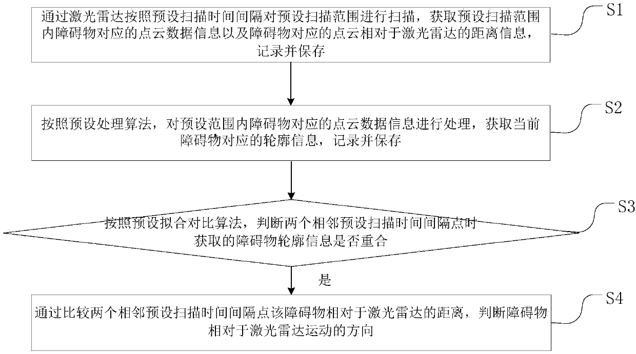
[0067] This embodiment provides a method for detecting the moving direction of obstacles based on laser radar, such as Figure 1 to Figure 4 As shown, the method includes the steps of:

[0068] A method for detecting the direction of movement of obstacles based on laser radar, comprising steps:

[0069] S1: Use the laser radar to scan the preset scanning range according to the preset scanning time interval, obtain the point cloud data information corresponding to the obstacle in the preset scanning range and the distance information of the point cloud corresponding to the obstacle relative to the laser radar, record and save;

[0070] S2: According to the preset processing algorithm, process the point cloud data information corresponding to the obstacle within the preset range, obtain the contour information corresponding to the current obstacle, record and save it;

[0071] S3: According to the preset fitting comparison algorithm, it is judged whether the obstacle contour i...

Embodiment 2

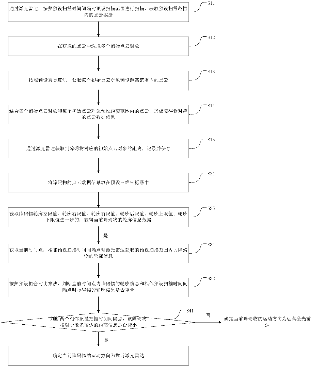
[0100] This embodiment provides a system for detecting the direction of movement of obstacles based on laser radar, such as Figure 5 to Figure 6 As shown, the system includes:

[0101] A system for detecting the direction of movement of obstacles based on lidar, including:

[0102] The acquisition data information module is used to scan the preset scanning range through the laser radar according to the preset scanning time interval, and obtain the point cloud data information corresponding to the obstacle in the preset scanning range and the point cloud corresponding to the obstacle relative to the laser radar. Distance information, record and save;

[0103] The calculation contour information module is used to process the point cloud data information corresponding to the obstacle within the preset range according to the preset processing algorithm, obtain the contour information corresponding to the current obstacle, record and save it;

[0104] The contour coincidence com...


PUM


Abstract

The invention provides a method for detecting obstacle movement direction based on a laser radar. The method is used for solving the problem that in the prior art, algorithm is complex and a pluralityof data needs to be processed in obstacle movement direction recognition. The method comprises the following steps of S1, obtaining a preset scanning time interval, point cloud data information corresponding to an obstacle in a preset scanning range, and distance information of the point cloud corresponding to the obstacle relative to the laser radar through the laser radar; S2, acquiring outlineinformation corresponding to the current obstacle; S3, judging whether the obstacle outline information obtained at two adjacent preset scanning time interval points coincide or not according to a preset fitting comparison algorithm; and S4, if yes, judging the movement direction of the obstacle relative to the laser radar by comparing the distance between the obstacle and the laser radar at twoadjacent preset scanning time interval points. By the method, a small amount of data needs to be processed to judge the movement direction of the obstacle, so that the purpose of active obstacle avoidance is achieved.

Description

technical field [0001] The invention relates to the technical field of laser radar identification, in particular to a system for detecting the moving direction of obstacles based on laser radar. Background technique [0002] Lidar obtains point cloud information of the surrounding environment through scanning and ranging, which has high precision, long distance, fast speed, and is not affected by light. It has broad application prospects in the field of unmanned vehicles and robots. [0003] At present, obstacle detection methods based on point cloud data are mostly used in detection methods based on high-precision UAN maps and detection methods based on machine learning training models. [0004] Among them, the detection method based on the high-precision environmental map is to obtain a high-precision environmental map by splicing the point cloud data collected offline first, and then compare the difference between the online point cloud data and the environmental map to ...

Claims


Application Information

Patent Timeline
Patent Type & Authority Applications(China)
IPC IPC(8): G01S17/58G01S17/93
CPCG01S17/58G01S17/931
Inventor 胡远敏肖勇陈国华叶占国
Owner ZHEJIANG CRRC ELECTRIC VEHICLE CO LTD
Why Eureka
Try Eureka