Phase conjugate reflection bi-pass lighting confocal microscopic device

A phase conjugation and confocal microscopy technology, which is applied in the direction of measuring devices, optical devices, instruments, etc., can solve the problems that the measurement of large curvature surfaces cannot be realized, and it is difficult to improve the axial resolution, so as to improve point scanning resolution and improve Measuring the effect of resolution

Inactive Publication Date: 2012-12-12
HARBIN INST OF TECH
View PDF5 Cites 22 Cited by
  • Summary
  • Abstract
  • Description
  • Claims
  • Application Information

AI Technical Summary

Problems solved by technology

[0004] The lack of commonality between the existing double-pass illumination confocal measurement method and the confocal measurement method proposed by Minsky is that when measuring a surface with a large curvature, the reflected measurement light exceeds the collection aperture of the collecting objective lens due to the change of the surface normal direction, so , the system will not be able to measure large curvature surfaces
At the same time, the system resolution is also closely related to the numerical aperture of the collecting objective lens. The larger the numerical aperture, the higher the axial resolution. However, due to the limitation of the principle that the imaging numerical aperture of the traditional lens is less than 1, it is difficult for both of them to increase the numerical aperture. Aperture to further improve axial resolution

Method used


Image

  • Phase conjugate reflection bi-pass lighting confocal microscopic device
  • Phase conjugate reflection bi-pass lighting confocal microscopic device
  • Phase conjugate reflection bi-pass lighting confocal microscopic device

Examples


Embodiment Construction

[0021] Embodiments of the present invention will be described in detail below in conjunction with the accompanying drawings.

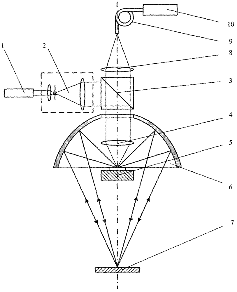
[0022] The phase conjugate reflective double-pass illumination confocal microscope device includes: laser 1, collimator beam expander 2, beam splitter 3, focusing objective lens 4, three-dimensional micro-displacement stage 5, collecting objective lens 8, conducting optical fiber 9, photodetector 10 wherein the collimating beam expander 2 and the beam splitter 3 are sequentially arranged on the direct light path of the laser 1, the focusing objective lens 4 and the three-dimensional micro-displacement stage 5 are arranged on the reflected light path of the beam splitter 3, and the collecting objective lens 8 is arranged on the transmission path of the beam splitter 3 On the optical path, the conducting optical fiber 9 conducts the light collected by the objective lens 8 to the photodetector 10, and an ellipsoidal reflector 6 is arranged on the reflectiv...


PUM


Abstract

The invention discloses a phase conjugate reflection bi-pass lighting confocal microscopic device, belonging to an optics measuring microtechnique. A collimation beam expander and a spectroscope are configured on a laser direct light path in sequence; a focusing objective lens and a three-dimensional micrometric displacement objective table are configured on a spectroscope reflecting light path; a collecting objective lens is configured on a spectroscope transmission light path; a collecting objective lens converging light is conducted to a photoelectric detector through conduction optical fibers; an ellipsoid reflecting lens is also configured on the spectroscope reflecting light path; a near focus of the ellipsoid reflecting lens is located on a surface of a sample put on the three-dimensional micrometric displacement objective table; and a phase conjugate reflecting lens is configured at a remote focus of the ellipsoid reflecting lens. According to the device, bi-pass lighting to a large curvature convex surface is carried out by adopting a characteristic that a reflection ray as a phase conjugate light wave of an incidence light of the phase conjugate reflecting lens can go back along an original way in combination with a characteristic that the ellipsoid reflecting lens is provided with a pair of isoplanatic image formation conjugate focuses, so that the device has a measurement ability of the large curvature convex surface and a characteristic of a high axial resolution force.

Description

technical field [0001] The invention belongs to optical microscopic measurement technology, and mainly relates to an ultra-precise measuring instrument for three-dimensional microstructure, microstep, microgroove line width, depth and surface shape measurement in microstructured optical elements, microstructured mechanical elements, and integrated circuit elements. Non-contact measuring device. Background technique [0002] Confocal scanning measurement is one of the important technical means to measure three-dimensional microstructure, micro-step, micro-groove line width, depth and surface shape in the fields of micro-optics, micro-mechanics and micro-electronics. The basic idea is to introduce a pinhole detector Stray light is suppressed and axial tomography capability is produced, but traditional confocal technology has always been limited by the principle that the numerical aperture of traditional lens imaging is less than 1. [0003] Double-pass illumination confocal m...

Claims


Application Information

Patent Timeline
Patent Type & Authority Applications(China)
IPC IPC(8): G01B9/04G01B11/00G01B11/02G01B11/22G01B11/30
Inventor 刘俭谭久彬
Owner HARBIN INST OF TECH
Why Eureka
Try Eureka