
Active monitoring system and method thereof

A monitoring system and active technology, applied in general control systems, control/regulation systems, program control, etc., can solve the problems of ineffective real-time monitoring, inability to effectively perform real-time monitoring, occupation of bandwidth, etc., to improve monitoring efficiency and The effect of bandwidth utilization

Active Publication Date: 2010-06-16
MOXA INC
View PDF0 Cites 3 Cited by
  • Summary
  • Abstract
  • Description
  • Claims
  • Application Information

AI Technical Summary

Problems solved by technology

[0003] However, when the above-mentioned monitoring system needs to add monitoring equipment, since the added equipment may come from different hardware manufacturers, and each equipment is equipped with exclusive monitoring software, how to make the data exchange interfaces of these equipment compatible becomes a problem. One of the problems that hardware manufacturers are eager to solve
[0004] In view of this, various hardware manufacturers and software manufacturers jointly proposed an open industrial communication standard interface (namely OLE for Process Control, OPC) to enable different monitoring software to connect and exchange data with devices of different hardware manufacturers. However, since the OPC detection and monitoring device uses polling, real-time monitoring cannot be effectively performed, and the problem of occupying bandwidth will also arise due to the limitation of the polling method
[0005] To sum up, it can be known that the prior art has long been unable to effectively perform real-time monitoring and occupy bandwidth. Therefore, it is necessary to propose improved technical means to solve this problem.

Method used

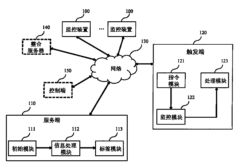
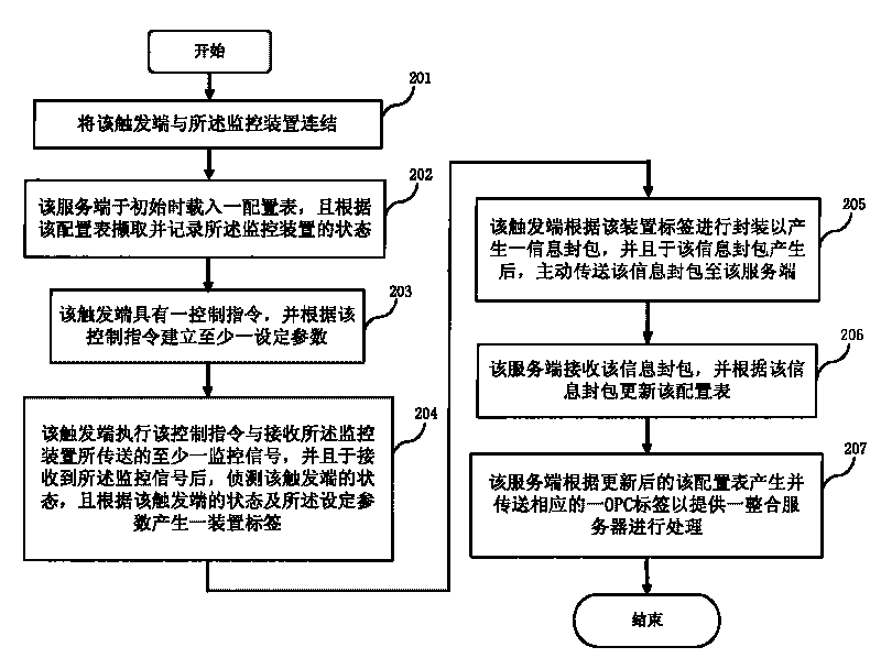
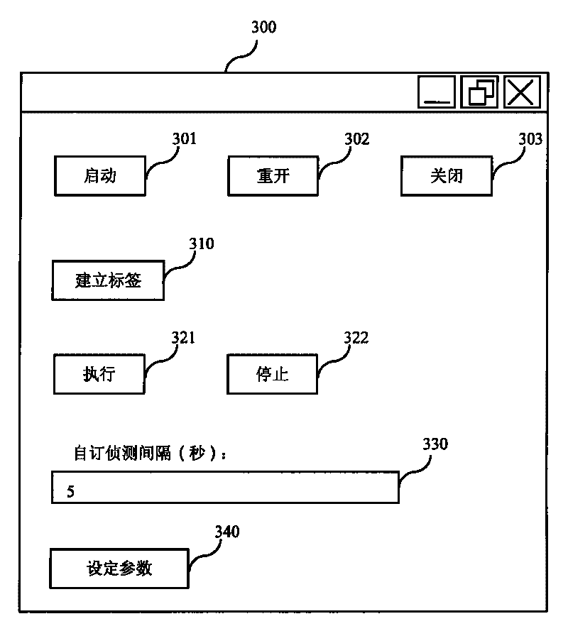

Image

  • Active monitoring system and method thereof
  • Active monitoring system and method thereof
  • Active monitoring system and method thereof

Examples


Embodiment Construction

[0016] The embodiments of the present invention will be described in detail below with the drawings and examples, so as to fully understand and implement the implementation process of how the present invention applies technical means to solve technical problems and achieve technical effects.

[0017] Before explaining the active monitoring system and method disclosed in the present invention, the framework of the present invention and the terms defined by itself are explained as follows. First, in the part of the framework, the system of the present invention includes a server, a trigger and a network. The server end is an OPC server (OPC Server), and this OPC server can receive the information package that is actively transmitted by the trigger end, and generate an OPC tag that meets the OPC standard to perform data exchange processing; and the trigger end can have an input / Output ports (DigitalInput, DI; Digital Output, DO) and programmable logic controllers that can execute...


PUM


Abstract

An active monitoring system and a method thereof are used for solving the problem that real-time monitoring cannot be effectively performed and bandwidth is occupied. A trigger end detects a monitoring device to generate a device tag, and the device tag is encapsulated and actively transmitted to a service end through a network, so that the service end automatically produces an industrial communication standard interface (namely, OLE for Process Control, OPC) tag for an integration server to fulfill the aim of improving the monitoring efficiency and the bandwidth utilization ratio.

Description

technical field [0001] The present invention relates to an active monitoring system and its method, in particular to an active monitoring system and its method enabling the trigger end to actively transmit device labels. Background technique [0002] In recent years, with the vigorous development of semiconductor-related industries and networks, the monitoring system has become more mature and has a wider range of applications. For example, operators can directly monitor remote equipment through the Internet without having to personally The same result can be obtained by operating in front of the equipment. In this way, not only the manpower can be streamlined, but also the cost can be effectively reduced. [0003] However, when the above-mentioned monitoring system needs to add monitoring equipment, since the added equipment may come from different hardware manufacturers, and each equipment is equipped with exclusive monitoring software, how to make the data exchange interf...

Claims


Application Information

Patent Timeline
Patent Type & Authority Applications(China)
IPC IPC(8): G05B19/048
Inventor 黄宗琦林启仁程冠卫
Owner MOXA INC
Learn More