
Locking circuit for overvoltage-undervoltage protection of driving voltage of IGBT (insulated gate bipolar transistor)

An overvoltage, undervoltage, driving voltage technology, applied in the direction of emergency protection circuit device, emergency protection circuit device, circuit device for limiting overcurrent/overvoltage, etc. Low, complex and other problems, to achieve the effect of reliable and practical circuit performance, fast response speed and low cost

Active Publication Date: 2012-01-11
NANJING APAITEK TECH
View PDF0 Cites 0 Cited by
  • Summary
  • Abstract
  • Description
  • Claims
  • Application Information

AI Technical Summary

Problems solved by technology

The ideal voltage of the IGBT driver chip is generally between 14-16V. The ideal state is: when the amplitude of the power supply voltage is lower than 14V or higher than 16V, the PWM signal is blocked and cannot reach the gate of the IPM. The pole is pulled down; when the power supply voltage is between 14V-16V, the PWM signal can pass through the circuit smoothly, and reach the gate of the IGBT with an amplitude of 14V-16V; there are many existing detection and protection locking circuits, or they are relatively complicated. Either the cost is relatively expensive, so a new circuit needs to be developed to achieve protection and locking

Method used


Image

  • Locking circuit for overvoltage-undervoltage protection of driving voltage of IGBT (insulated gate bipolar transistor)
  • Locking circuit for overvoltage-undervoltage protection of driving voltage of IGBT (insulated gate bipolar transistor)

Examples


Embodiment Construction

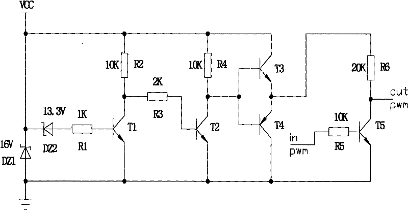
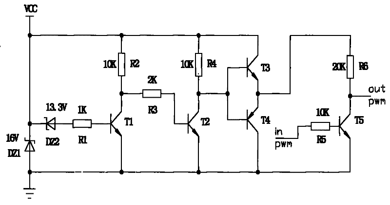
[0016] Below in conjunction with accompanying drawing, technical content of the present invention is described:

[0017] Such as figure 1 As shown, the overvoltage and undervoltage protection locking circuit of the IGBT drive voltage of the present invention includes 2 voltage regulator tubes, 6 resistors and 5 triodes, and a 17V voltage regulator tube DZ1 is connected in series with VCC , the anode is grounded, and the cathode of the Zener tube DZ1 is connected in parallel with a 14.3V Zener tube DZ2 (in the above, DZ1 is 16V, DZ2 is 13.3V, because T3 has a voltage drop of about 1V, so the actual value is 17V and 14.3V respectively ), the anode is connected in series with a 1K resistor R1 to the base of the NPN transistor T1, the collector of T1 is connected in series with a 10K resistor R2 and then connected to VCC, and the collector output of T1 is connected in series with a 2K resistor and then connected to the NPN transistor T2 The base of T2, the collector of T2 is conn...


PUM


Abstract

The invention discloses a locking circuit for the overvoltage-undervoltage protection of a driving chip of an IGBT (insulated gate bipolar transistor), which has reliable and practical performance. The circuit comprises voltage regulator tubes, resisters and a triode, wherein a voltage regulator tube DZ1 of 16V is connected in series on a VCC, the anode of the voltage regulator tube DZ1 is earthed, the cathode of the voltage regulator tube DZ1 is connected in parallel with a voltage regulator tube DZ2 of 13.3V, the anode of the voltage regulator tube DZ2 is connected in series with a resisterR1 of 1K and then connected to the base of an NPN triode T1, the collector electrode of the T1 is connected in series with a resister R2 of 10K and then connected to the VCC, simultaneously, the collector electrode output of the T1 is connected in series with a resister of 2K and then connected to the base of an NPN triode T2, the collector electrode of the T2 is connected in series with a resister R4 of 10K and then connected to the VCC, simultaneously, the collector electrode output of the T2 is connected with the input end of a push-pull circuit, the output end of the push-pull circuit is connected in series with a resister R6 of 20K and then connected to the collector electrode of an NPN triode T5 and connected with a PWM signal output end, the base of the T5 is connected in series with a resister R5 of 10K and then connected to a PWM signal input end, and emitters of the T1, the T2 and the T5 are all earthed.

Description

technical field [0001] The invention relates to a circuit, more specifically to an overvoltage and undervoltage protection locking circuit of an IGBT driving voltage, and belongs to the field of power electronics. Background technique [0002] IGBT is an expensive component among many electronic components, and it is very sensitive to the magnitude and stability of the gate operating power supply voltage during operation, and must be within a suitable range, otherwise the gate may be broken down. Extreme or not in normal working condition and other problems. The ideal voltage of the IGBT driver chip is generally between 14-16V. The ideal state is: when the amplitude of the power supply voltage is lower than 14V or higher than 16V, the PWM signal is blocked and cannot reach the gate of the IPM. The pole is pulled down; when the power supply voltage is between 14V-16V, the PWM signal can pass through the circuit smoothly, and reach the gate of the IGBT with an amplitude of 14...

Claims


Application Information

Patent Timeline
Patent Type & Authority Patents(China)
IPC IPC(8): H02H9/04
Inventor 石泉
Owner NANJING APAITEK TECH
Learn More