An electronic proximity switch
A proximity switch, electronic technology, applied in the field of electronic proximity switches, can solve the problems of complex wiring, poor shock resistance, difficult installation, etc., and achieve the effect of simple wiring operation, strong shock resistance and stable performance
- Summary
- Abstract
- Description
- Claims
- Application Information
AI Technical Summary
Problems solved by technology
Method used
Image
Examples
Embodiment 1
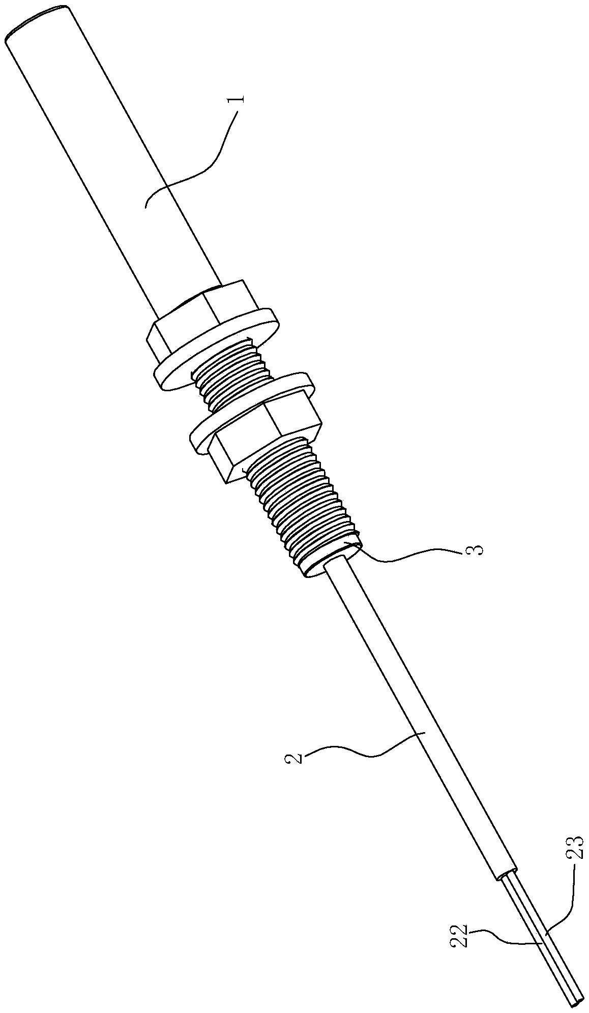
[0027] see figure 1 and figure 2 , an electronic proximity switch, comprising a switch base 1 and a switch body 2, the switch body 2 is provided with a switch housing cover 3, the part of the switch body 2 located on the side of the switch housing cover 3 is inserted into the switch base 1, the switch The part of the main body 2 located on the other side of the switch housing cover 3 extends out of the switch base 1 , and the switch housing cover 3 abuts against the bottom of the switch base 1 .
[0028] The part of the switch main body 2 inside the switch base 1 includes a PCB circuit board 21, and the PCB circuit board 21 includes an MR magnetoresistive chip 211, which can sense changes in the magnetic field of an external magnet and output high or low levels. For example, when the external magnetic field is sensed from low level to high level, it outputs high level, when the magnetic field is far away, it still outputs high level, and only when it senses the opposite mag...
Embodiment 2
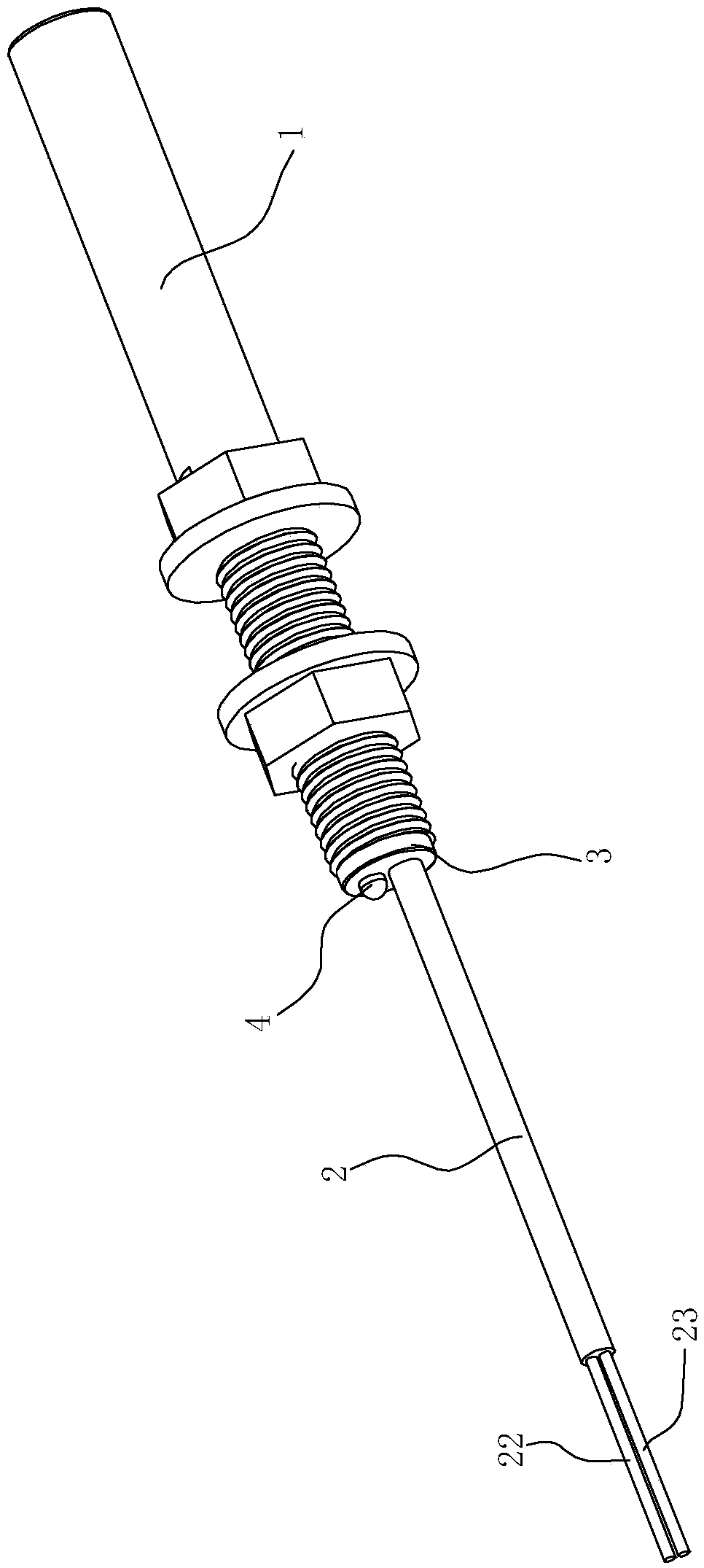
[0032] see image 3 and Figure 4 , in this embodiment, the difference from the first embodiment above is that it also includes an LED indicator light 4, which is connected with the switch circuit on the PCB circuit board 21, and is used to monitor the working state of the proximity switch at any time, and determine whether the proximity switch is Abnormally, the proximity switch is highly resistant to vibration. A mounting hole 31 is provided on the switch housing cover 3, and the indicator light 4 passes through the switch housing cover 3 through the mounting hole 31, so that the light-emitting part is exposed outside the switch base 1, and can be visually monitored from the outside.
[0033] see Figure 5 , the circuit on the PCB circuit board 21 is a bistable switch circuit composed of MR reluctance chip 211 and other electronic components, except MR reluctance chip 211, also includes voltage stabilizing circuit 212 and analog switch Q1, voltage stabilizing circuit 212 ...
PUM
 Abstract
Description
Claims
Application Information
 - R&D
- Intellectual Property
- Life Sciences
- Materials
- Tech Scout
- Unparalleled Data Quality
- Higher Quality Content
- 60% Fewer Hallucinations
Browse by: Latest US Patents, China's latest patents, Technical Efficacy Thesaurus, Application Domain, Technology Topic, Popular Technical Reports.
© 2025 PatSnap. All rights reserved.Legal|Privacy policy|Modern Slavery Act Transparency Statement|Sitemap|About US| Contact US: help@patsnap.com


