Hydraulic pump for excavator, and excavator with same

A technology for excavators and hydraulic pumps, which is applied in the field of hydraulic pumps, and can solve problems such as affecting the efficient operation of hydraulic pumps and excessive vibration of drive shafts

Inactive Publication Date: 2014-06-25
BOSCH REXROTH BEIJING HYDRAULIC
View PDF0 Cites 5 Cited by
  • Summary
  • Abstract
  • Description
  • Claims
  • Application Information

AI Technical Summary

Problems solved by technology

If this bending moment or centrifugal force is too large, it will also cause excessive vibration of the drive shaft, which will affect the efficient work of the hydraulic pump

Method used


Image

  • Hydraulic pump for excavator, and excavator with same
  • Hydraulic pump for excavator, and excavator with same
  • Hydraulic pump for excavator, and excavator with same

Examples


Embodiment Construction

[0023] Illustrative embodiments of the present invention are described below with reference to the accompanying drawings. It should be noted that the same reference numerals in the drawings represent elements or components with the same function and / or structure.

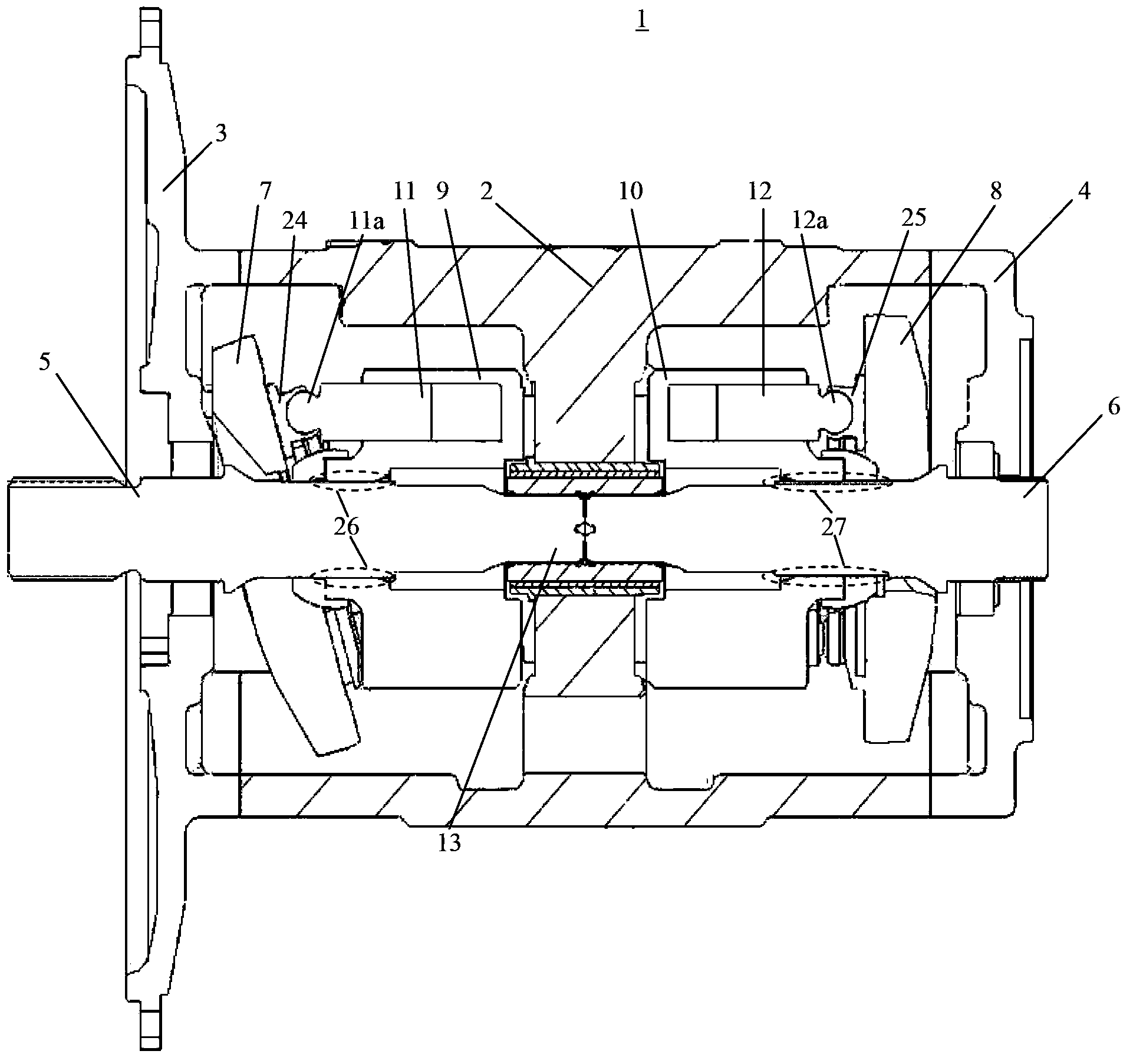
[0024] figure 1 A schematic axial sectional view of a hydraulic pump 1 according to an embodiment of the invention is shown. The hydraulic pump according to the invention can be used in harsh machinery such as excavators.

[0025] like figure 1 As shown, a hydraulic pump 1 comprises a housing 2 and end covers 3 , 4 mounted at both ends of said housing 2 . Two rotating shafts 5, 6; two rotary hydraulic cylinders 9, 10; and two swash plates 7, 8 for driving the rotary hydraulic cylinders are installed in the housing 2. The swash plates 7 and 8 are used to adjust the working strokes of the rotary hydraulic cylinders 9 and 10 respectively.

[0026] The two rotational shafts 5 , 6 are arranged coaxially and their op...


PUM


Abstract

The invention relates to a hydraulic pump for an excavator. The hydraulic pump comprises a shell, a pair of rotary hydraulic cylinders arranged in the shell, and a pair of rotating shafts arranged parallelly to the rotary hydraulic cylinders, a supporting wall extends in the shell, a piston capable of reciprocating is arranged in each rotary hydraulic cylinder, the rotating shafts are connected through a coupler and used for driving the rotary hydraulic cylinders to rotate around the central axes, and an inclined disc used for receiving and guiding the corresponding piston is arranged for each rotary hydraulic cylinder and fixed relatively to the corresponding rotating shaft. The hydraulic pump is characterized in that the supporting wall is provided with a mounting hole, and the coupler is supported in the mounting hole through a sliding bearing. The invention further relates to the excavator comprising the hydraulic pump.

Description

technical field [0001] The invention relates to a hydraulic pump, in particular a hydraulic pump for an excavator, and also to an excavator having such a hydraulic pump. Background technique [0002] Hydraulic pumps used in excavators typically include a housing and a pair of rotary hydraulic cylinders housed within the housing. The rotary hydraulic cylinders are coaxially arranged opposite to each other. A drive shaft is supported within the housing parallel to the longitudinal axis of the rotary cylinder. Two swash plates are respectively fixedly mounted in the housing relative to the drive shaft. A reciprocating piston is arranged in the rotary hydraulic cylinder. A mating surface is provided in each swash plate for receiving and guiding the pistons. As the drive shaft rotates, each rotary hydraulic cylinder is also driven to rotate around the central axis of the drive shaft, thereby driving the piston to reciprocate in the respective rotary hydraulic cylinder. [00...

Claims


Application Information

Patent Timeline
Patent Type & Authority Applications(China)
IPC IPC(8): E02F9/22
CPCF04B39/0284F04B1/324F04B1/2071F04B1/20F04B1/22
Inventor R·沙芬博格林晟
Owner BOSCH REXROTH BEIJING HYDRAULIC
Why Eureka
Try Eureka