Dynamic vibration absorber-based device for collecting piezoelectric vibration energy
A dynamic vibration absorber and energy harvesting technology, applied in piezoelectric/electrostrictive or magnetostrictive motors, electrical components, generators/motors, etc. Effect
- Summary
- Abstract
- Description
- Claims
- Application Information
AI Technical Summary
Problems solved by technology
Method used
Image
Examples
Embodiment 1
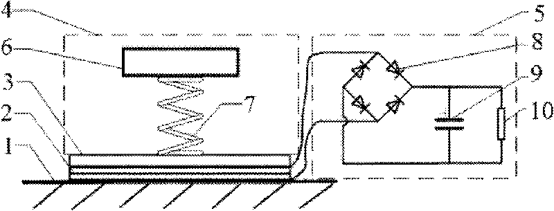
[0021] Such as figure 1 As shown, this embodiment includes: a vibrating element 1, a piezoelectric element 2, a cover plate 3, a dynamic vibration absorber 4 and an energy harvesting circuit 5, wherein: the vibrating element 1 is connected to the piezoelectric element 2, and the piezoelectric element 2 is fixed with a cover The plate 3 and the cover plate 3 are connected with the dynamic shock absorber 4 , and the energy harvesting circuit 5 is connected with the piezoelectric element 2 .
[0022] The dynamic vibration absorber 4 includes: a mass block 6 and an elastic element 7 , wherein: the elastic element 7 is connected to the cover plate 3 , and the mass block 6 is connected to the elastic element 7 .
[0023] The damping ratio of the elastic element 7 is less than 0.3.
[0024] Piezoelectric element 2 of the present embodiment adopts thickness stretching mold, and its piezoelectric constant is d 33 .
[0025] The energy harvesting circuit 5 is a full-bridge rectifier ...
Embodiment 2
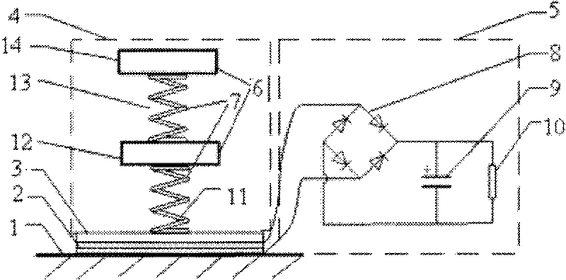
[0030] Such as figure 2 As shown, the dynamic vibration absorber 4 of this embodiment is a superposition of two elastic elements 7 and a mass block 6, forming a double-layer dynamic vibration absorbing structure. The dynamic shock absorber 4 includes a first spring 11, a first mass block 12, a second spring 13 and a second mass block 14, wherein: the first spring 11 is connected to the cover plate 3, the first spring 11, the first mass block 12, The second spring 13 and the second mass block 14 are connected in sequence. That is, the elastic element 7 includes: a first spring 11 and a second spring 13 , and the mass block 6 includes: a first mass block 12 and a second mass block 14 .
[0031] Other implementation modes of this embodiment are the same as Embodiment 1.
[0032] In this embodiment, two springs, a mass block 6 and a vibrating element 1 are used to form a three-degree-of-freedom vibration system, which increases the number of formants and the width of the resona...
Embodiment 3
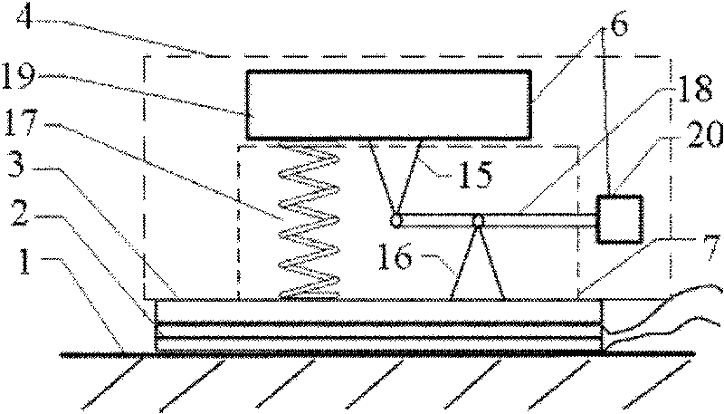
[0034] Such as image 3As shown, the elastic element 7 of this embodiment includes: a first bracket 15, a second bracket 16, a third spring 17 and a first lever 18, and the mass block 6 includes: a third mass block 19 and a fourth mass block 20, wherein : the first support 15 and the fourth mass block 20 are located at the two ends of the first lever 18 respectively, the second support 16 is connected to the first lever 18 and the cover plate 3 respectively, the first support 15 is connected to the third mass block 19, and the second support 16 is connected to the first lever 18 and the cover plate 3 respectively. The three masses 19 are connected to the third spring 17 , and the third spring 17 is connected to the cover plate 3 .
[0035] Other implementation modes of this embodiment are the same as Embodiment 1.
[0036] This structure is suitable for applications where weight is limited.
PUM
 Abstract
Description
Claims
Application Information
 - R&D
- Intellectual Property
- Life Sciences
- Materials
- Tech Scout
- Unparalleled Data Quality
- Higher Quality Content
- 60% Fewer Hallucinations
Browse by: Latest US Patents, China's latest patents, Technical Efficacy Thesaurus, Application Domain, Technology Topic, Popular Technical Reports.
© 2025 PatSnap. All rights reserved.Legal|Privacy policy|Modern Slavery Act Transparency Statement|Sitemap|About US| Contact US: help@patsnap.com


