

Device capable of preventing valuables from being damaged in earthquake
A technology of valuables and shock meters, which is applied in the direction of preventing mechanical damage, such as containers, transportation and packaging, and display stands. It can solve problems such as unstable center of gravity, high loading platform, and damage to the range of motion, and achieve compact devices and reduced installation. volume effect
- Summary
- Abstract
- Description
- Claims
- Application Information
AI Technical Summary
Problems solved by technology
Method used
Image

Examples
Embodiment Construction
[0078] The specific embodiment of the device for protecting valuables from earthquakes and other damages of the present invention will be further described below in conjunction with the accompanying drawings:
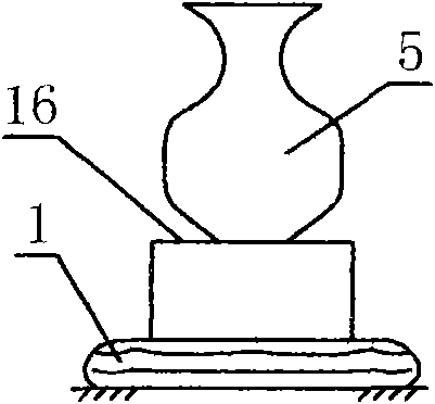
[0079] figure 1 As shown: the valuables 5 are placed on the table top of the booth 16, the unexpanded airbag 1 is stored in the outer periphery of the bottom of the table top of the booth, and the bottom of the airbag is fixed with the booth;
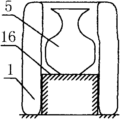
[0080] figure 2 As shown: the airbag 1 is inflated and unfolded in the shape of a hollow cylinder, the lower part of the airbag is fixed with the booth 16, and the valuables 5 are placed in the center of the airbag to be protected;
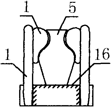
[0081] image 3 As shown: the outer airbag and the inner airbag are arranged on the periphery of the valuables 5, the inner airbag is hung on the outer airbag, the lower part of the outer airbag is fixed and deployed with the booth 16, and the inner airbag is deployed close to the upper surface of...
PUM
 Abstract
Description
Claims
Application Information