Lifting mechanism for a sliding roof and a vehicle roof with such mechanism

A technology for connecting mechanisms and vehicles, which can be used in transportation and packaging, roofs, vehicle parts, etc., and can solve the problem of large installation volume

Inactive Publication Date: 2007-05-30
ARVINMERITOR GMBH
View PDF0 Cites 7 Cited by
  • Summary
  • Abstract
  • Description
  • Claims
  • Application Information

AI Technical Summary

Problems solved by technology

A disadvantage of these configurations is that the installation volume of the bracket device in the longitudinal direction of the vehicle, as well as the bracket, lever and guide rail in the vertical direction, is relatively large

Method used


Image

  • Lifting mechanism for a sliding roof and a vehicle roof with such mechanism
  • Lifting mechanism for a sliding roof and a vehicle roof with such mechanism
  • Lifting mechanism for a sliding roof and a vehicle roof with such mechanism

Examples


Embodiment Construction

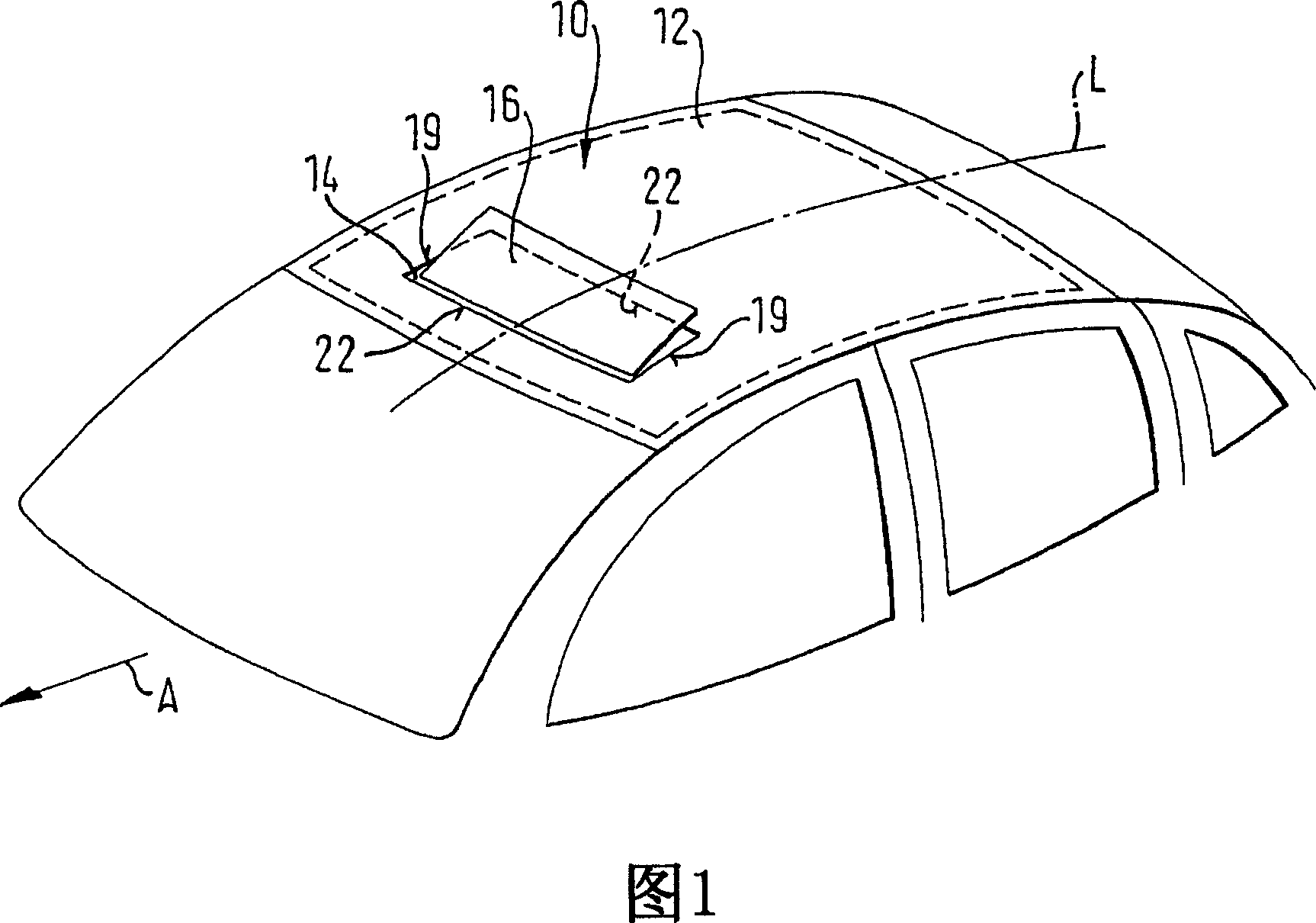
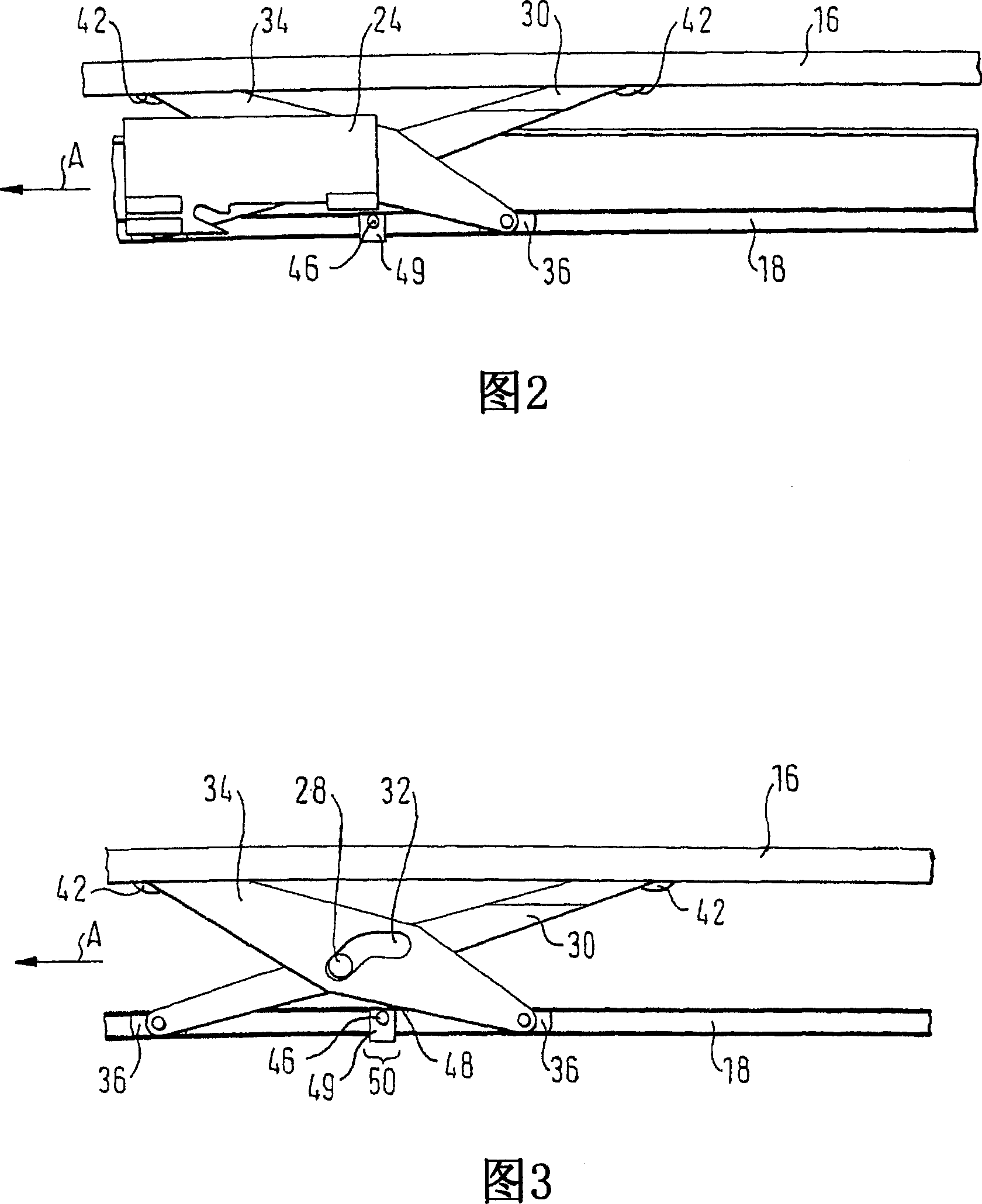
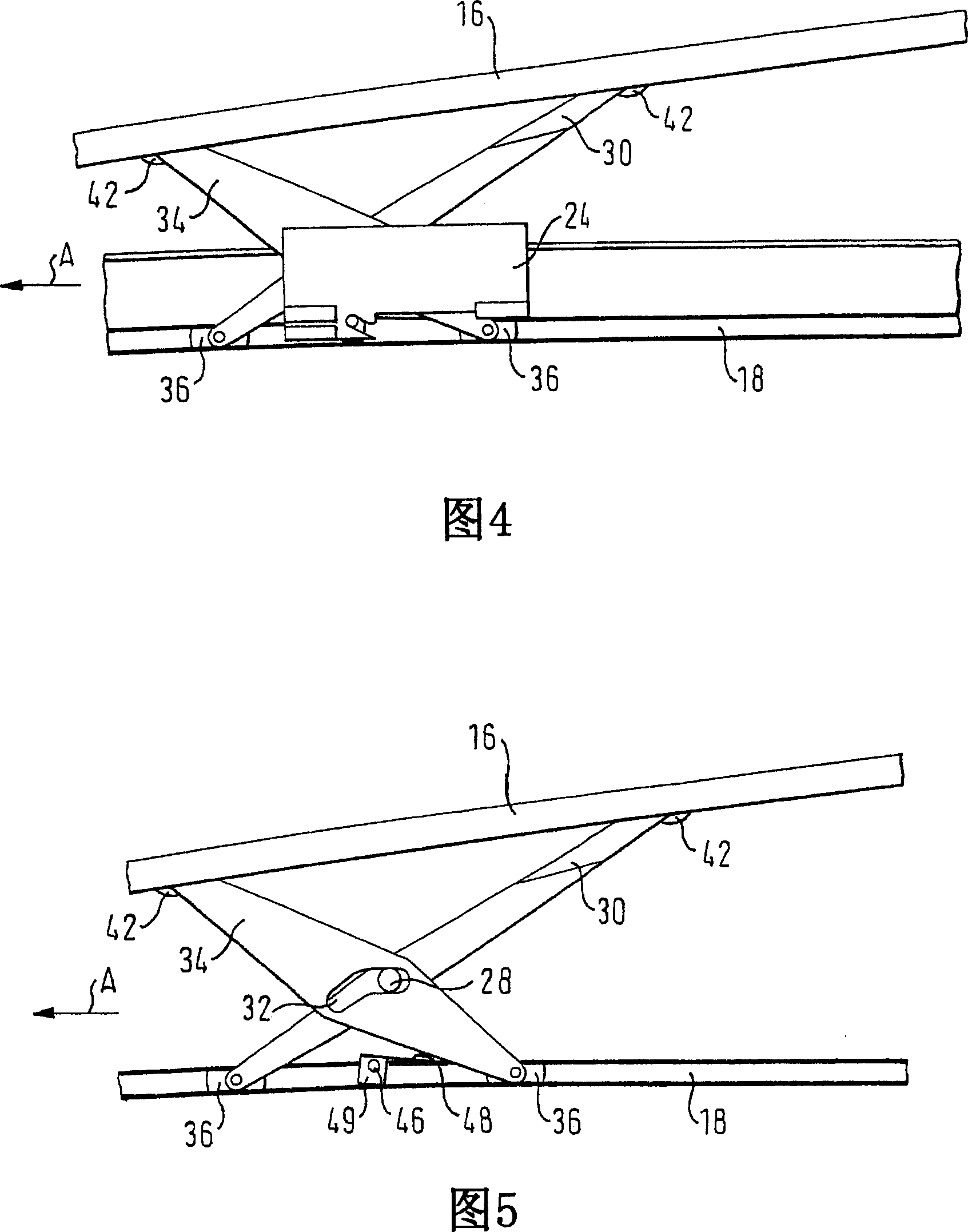
[0034] Figure 1 schematically shows a vehicle roof 10 comprising a stationary roof portion 12 in which a roof opening 14 is arranged, said roof opening 14 being closable by a cover 16 (cf Figures 2 and 3) Or exposed (see FIG. 6), the cover 16 is made of a visually transparent or opaque material. In Figures 1, 4 and 5, the cover 16 is shown in the venting position, with the cover 16 raised at its rear end.

[0035] The roof 10 shown is a sliding roof, in particular a spoiler roof, in which the cover 16 is moved over the stationary roof portion 12 . The roof 10 can also be embodied as comprising a sliding-tilt roof; in this case (not shown), the cover 16 will be moved to be positioned under the stationary roof portion 12 .

[0036] On each side of the top opening 14, the lifting mechanism for the cover 16 has a rail 18 (Figs. 1 to 6) affixed to the stationary top part 12 surrounding the top opening 14 and extending The opening 14 extends with a longitudinal side 19 which exten...


PUM


Abstract

The invention relates to a raising mechanism for a sliding roof, comprising a guide rail, a pair of levers, and a carriage. Each lever has a guide rail side end and a cover side end, and the levers are pivotally coupled with each other through a joining axle. During traversing movement, the carriage exerts a vertical force on the joining axle and lifts the joining axle, in order to thereby move the pair of levers to a raised position. The invention further relates to a vehicle roof with such a raising mechanism.

Description

technical field [0001] The invention relates to a lifting mechanism for a sliding roof, and further to a vehicle roof comprising such a lifting mechanism. Background technique [0002] The sliding roof of the vehicle has at least one cover which can be fully or partly exposed by first raising said cover at its rear end or in a ventilation position. [0003] Mechanisms are known from the prior art which use several carriages for lifting and moving the cover, each of which can be moved in a side guide. Through the cooperation between the bracket and the guide rail, on the one hand a lifting action is produced, by means of which the corresponding cover can be moved upwards, and on the other hand a displacement action is produced. For this purpose, grooved guides are used in particular. A disadvantage of these configurations is that the installation volume of the bracket arrangement in the longitudinal direction of the vehicle, as well as the bracket, lever and guide rail in t...

Claims


Application Information

Patent Timeline
Patent Type & Authority Applications(China)
IPC IPC(8): B60J7/05
CPCB60J7/0435
Inventor 托马斯·贝歇尔霍斯特·伯姆雷纳·格里姆克劳迪娅·里斯约阿希姆·勒德尔曼弗雷德·罗恩克
Owner ARVINMERITOR GMBH
Why Eureka
Try Eureka