Device for correcting precision of rack installation surface of lathe body of lathe

A lathe bed and mounting surface technology, which is applied in the field of large and heavy CNC lathes, can solve the problems of excessive precision, bed deformation, and insufficiency, and achieve the effects of easy guarantee of position tolerance, high processing efficiency, and reduced labor intensity of workers

Inactive Publication Date: 2010-06-23
ANYANG XINSHENG MACHINE TOOL
View PDF0 Cites 4 Cited by
  • Summary
  • Abstract
  • Description
  • Claims
  • Application Information

AI Technical Summary

Problems solved by technology

[0003] The purpose of the present invention is to overcome the lack of capability of the original processing equipment and the out-of-tolerance problem of the position accuracy of the bed rack mounting surface and the reference guide rail surface caused by the deformation caused by the complex structure, so as to ensure that the machined lathe bed rack mounting surface and The position tolerance requirement of the guide surface of the guide rail is convenient for installation and debugging,

Method used


Image

  • Device for correcting precision of rack installation surface of lathe body of lathe
  • Device for correcting precision of rack installation surface of lathe body of lathe

Examples


Embodiment Construction

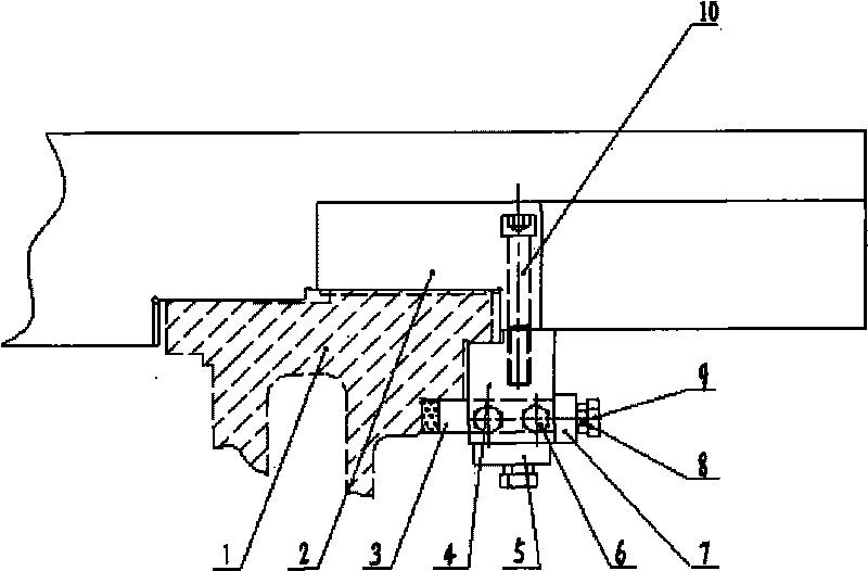
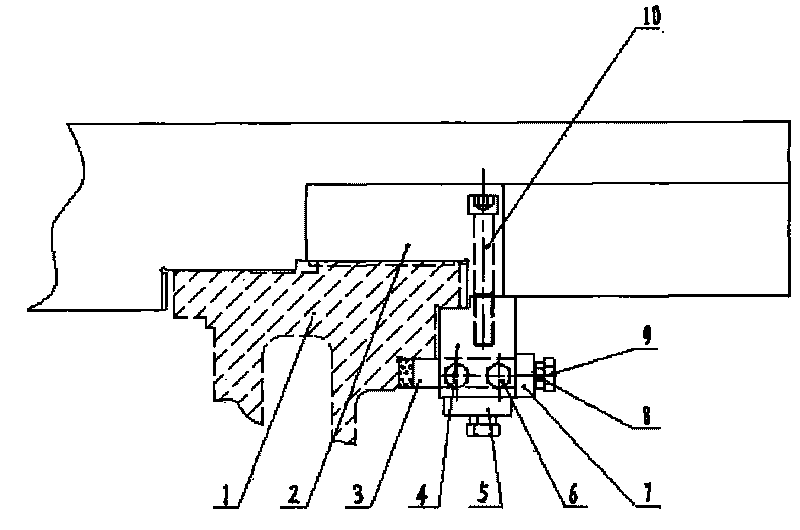
[0016] Such as figure 1 As shown, the present invention includes a tool holder 4 arranged on the saddle 2 of the lathe, and is characterized in that: a tool 3 is installed in the tool holder 4, and the tool 3 is a wide-edged planer, and the tool holder 4 moves with the electric tailstock of the lathe Do synchronous movement to realize the correction of the rack mounting surface of the lathe bed 1.

[0017] The tool holder 4 is connected with the lathe saddle by screws 10 through the mounting hole of the pressure plate of the lathe saddle 2 . The cutter 3 (wide-edged planer 3) that is positioned in the tool holder 4 is fixed in the tool holder 4 by two compression bolts 6 that are arranged on the side of the tool holder.

[0018] At the rear of the tool holder 4, a front and rear adjustment plate 7 is provided, and an adjustment bolt 9 is threaded on the front and rear adjustment plate 7. Tightening lock nuts 8 are installed between the adjustment plates 7 , and the position ...


PUM


Abstract

The invention relates to a device for correcting the precision of a rack installation surface of a lathe body of a lathe, which is arranged on a lathe saddle of the lathe in the assembling process for correcting the rack installation surface of the lathe body of the lathe. The invention is suitable for large and heavy numerical control lathes with high installation precision requirement and long length specification. The device comprises a cutter clamp, wherein the cutter clamp is distributed and arranged on the lathe saddle of the lathe, a wide edge plane cutter is arranged in the cutter clamp, the cutter is regulated to a proper position through a regulation screw bolt arranged on a regulation plate, and then, the cutter is tightly pressed, the cutter clamp moves synchronously along with an electric tail seat of the lathe for realizing the correction on the rack installation surface of the lathe body of the lathe, the position tolerance between the corrected rack installation surface of the lathe body and the reference surface can be easily ensured, the precision requirement of the product drawing can be ensured, the work intensity of workers can be reduced, and the production efficiency can be improved.

Description

technical field [0001] The invention relates to a device for correcting the accuracy of the rack mounting surface of the lathe bed, which is installed on the saddle of the lathe bed during the assembly process and corrects the mounting surface of the rack of the lathe bed. Longer large and heavy CNC lathes. Background technique [0002] At present, the longitudinal feed of long lathes (large and heavy lathes) in China generally adopts rack and pinion transmission, which has strong rigidity and good stability. However, due to the long mounting surface of the rack, the processing of it and the guide surface of the Z-direction feed rail is not completed in one clamping, and the structure of the bed is complex and easy to deform, which may easily cause the position tolerance of the two sides to be out of tolerance. Our company's product CKH61125 / 8000 heavy-duty CNC lathe has the most serious parallelism between the mounting surface of the primary tooth bar and the guiding surfa...

Claims


Application Information

Patent Timeline
IPC IPC(8): B23D11/00
Inventor 吕安相何爱军郝利军刘天俊郭志强刘天来张安清刘苏峰李香文王洪明
Owner ANYANG XINSHENG MACHINE TOOL
Why Eureka
Try Eureka