
Torque-control multishaft bolt tightening machine

A technology for torque control and shaft bolts, applied in the direction of manufacturing tools, metal processing, metal processing equipment, etc., can solve problems such as affecting the accuracy and quality of workpieces, increasing the workload of workers, difficult management and control, etc., to improve work efficiency, Conducive to automatic control and simple structure

Inactive Publication Date: 2010-06-23
SHENYANG INST OF AUTOMATION - CHINESE ACAD OF SCI
View PDF0 Cites 24 Cited by
  • Summary
  • Abstract
  • Description
  • Claims
  • Application Information

AI Technical Summary

Problems solved by technology

When the assembled workpieces are in the same working plane or close to the same plane, and the number of bolts is large, if a single-axis tightening machine is used, the work efficiency will be very low, and the torque of the tightening head is controlled by people, which affects the accuracy of the workpiece. and quality, it is very inconvenient for workers to operate, and it increases the workload of workers, which seriously affects the work rhythm
In order not to affect the work progress, only increase the number of workers to make up for the lack of equipment functions, which will undoubtedly increase the production cost, and due to the increase in the number of workers, it will also make it difficult to manage and control

Method used


Image

  • Torque-control multishaft bolt tightening machine
  • Torque-control multishaft bolt tightening machine
  • Torque-control multishaft bolt tightening machine

Examples


Embodiment Construction

[0021] The present invention will be described in further detail below in conjunction with the accompanying drawings.

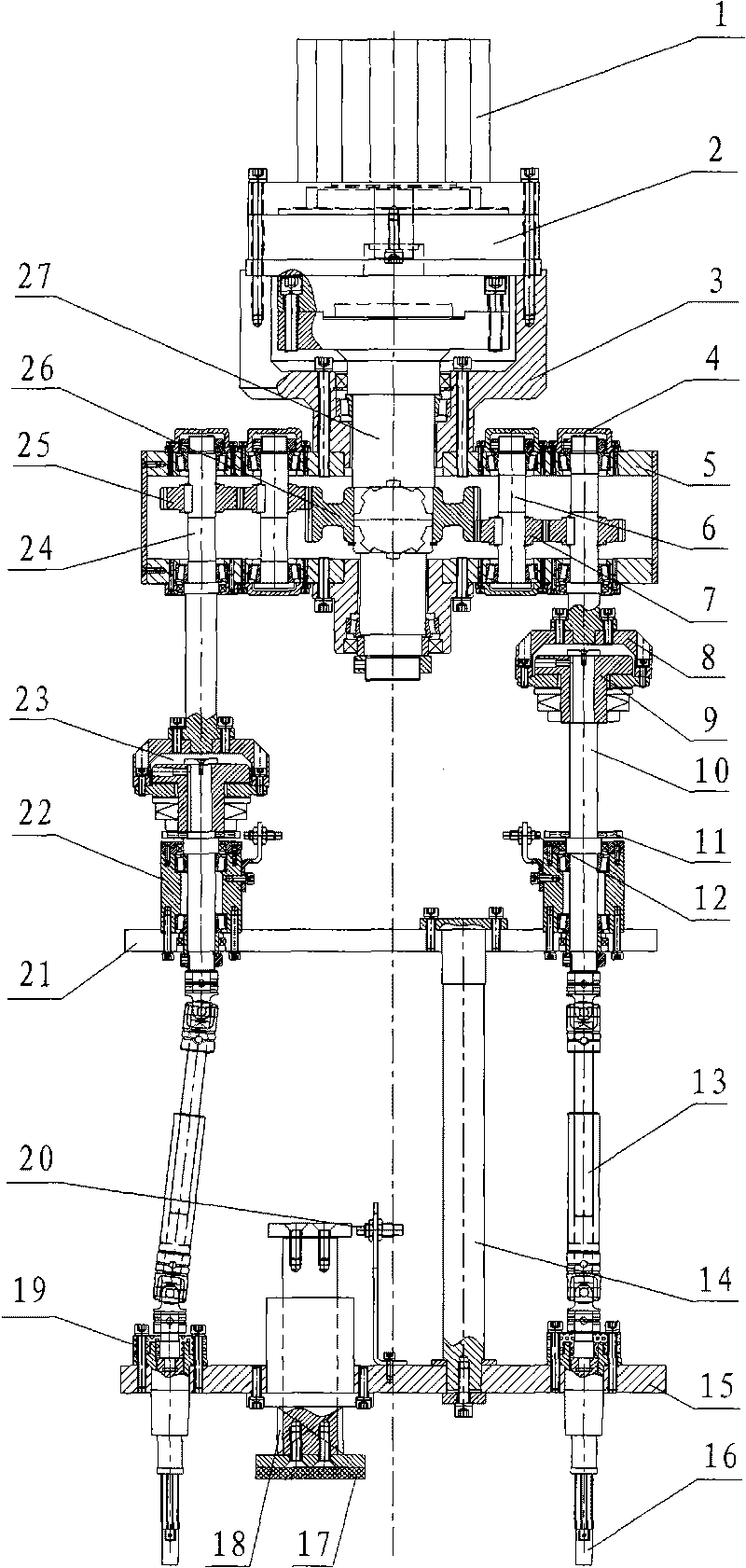
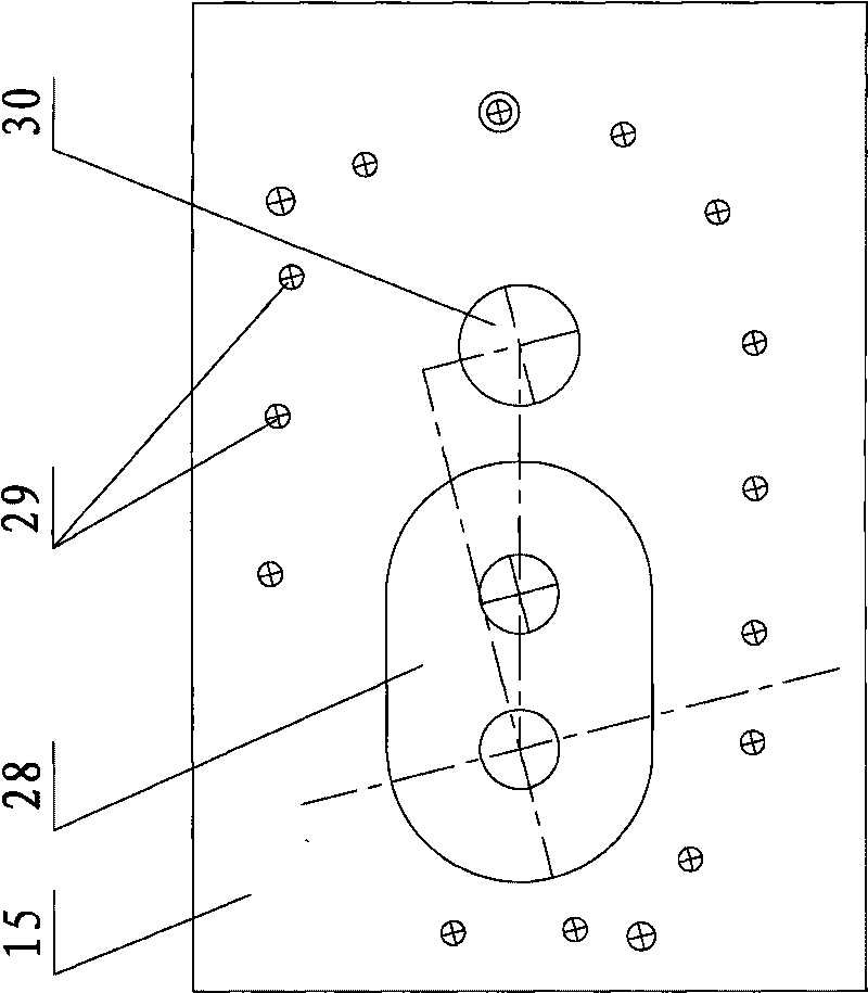
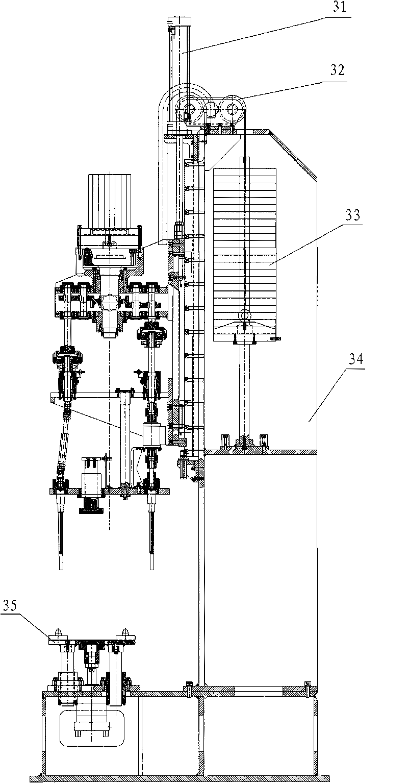
[0022] Such as figure 1 As shown, the present invention includes drive unit, transmission case 5, intermediate shaft 27, torque limiter 23 and tightening head 16, and drive unit is made up of motor 1, speed reducer 2 and speed reducer seat 3. The reducer 2 is installed on the reducer seat 3, and the motor 1 is connected with the reducer 2. One end of the intermediate shaft 27 is connected to the motor 1 through the reducer 2, and the other end passes through the transmission case 5 located below the reducer 2, and the reducer seat 3 is fixed on the transmission case 5; the intermediate shaft 27 is located in the transmission case 5 Part is affixed with intermediate gear 26, is provided with a plurality of transition shafts 6 (the present embodiment is fourteen) in transmission case 5 inside, the periphery of intermediate shaft 27, and transition gear 7 is al...


PUM


Abstract

The invention relates to bolt tightening devices, in particular to a torque-control multishaft bolt tightening machine which comprises a driving device, a gear box, an intermediate shaft, torque limiters and a tightening head, wherein one end of the intermediate shaft is connected with the driving device, and the other end penetrates out of the gear box; the outputs of the gear box are provided with transmission shafts, each transmission shaft is connected with an output shaft through the torque limiter, the other end of each output shaft is provided with a fixed plate, the output shaft at the end is connected with one end of a universal shaft after penetrating through the fixed plate, the other end of the universal shaft is connected with a template, and the tightening head is connected with the universal shaft through the template; and the template is provided with a limit switch, and one side of the limit switch is provided with a sensor fixedly connected on the template. The invention has the advantages of high efficiency, simple structure, high integration level, strong adaptability, wide application range and the like, and can realize multiple functions of reverse rotation, control on magnitude of moment, speed regulation and the like.

Description

technical field [0001] The invention relates to a bolt tightening device, in particular to a torque controlled multi-axis bolt tightening machine. Background technique [0002] Generally, the assembly line has many equipments and complex technologies, and there are many types of tightening machine tools used, which can be roughly divided into three types: electric single-axis tightening machine, electric multi-axis tightening machine and pneumatic single-axis tightening machine. Most of the electric multi-axis tightening machine transmits power through the pulley; the electric single-axis tightening machine is composed of a rotor and a stator, and the workpiece is tightened through the rotation of the rotor; the pneumatic single-axis tightening machine rotates the impeller through the airflow. The protection of the tightening machine is achieved by reducing the pressure through the pressure relief valve. When the assembled workpieces are in the same working plane or close t...

Claims


Application Information

Patent Timeline
Patent Type & Authority Applications(China)
IPC IPC(8): B23P19/06
Inventor 陈书宏刘国涛于龙会王海涛陈平徐凤春周永征
Owner SHENYANG INST OF AUTOMATION - CHINESE ACAD OF SCI
Learn More