
Connection structure of console and headlamp

A technology of instrumentation and structure, which is applied in the field of connection structure between instrumentation and headlights, and can solve problems such as instrumentation damage, severe vibration, and difficulty in achieving accuracy

Inactive Publication Date: 2010-06-23
KYMCO
View PDF0 Cites 3 Cited by
  • Summary
  • Abstract
  • Description
  • Claims
  • Application Information

AI Technical Summary

Problems solved by technology

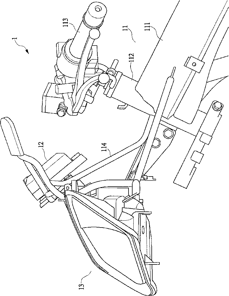
However, since the instrument 12 is fixed on the uppermost end of the front bracket 114, when the motorcycle 1 is running, it is quite easy to increase the vibration amplitude of the instrument 12, and then cause damage to the internal parts of the instrument 12, and the The exposure of the front bracket 114 also causes the appearance of the motorcycle 1 to be poor, and once the front bracket 114 is extended too long, the amplitude of its vibration will be more severe, so the front bracket 114 needs to be provided with a reinforcement structure; in addition, due to The existing headlight 13 and instrument 12 are assembled separately, so it is difficult to achieve the accuracy of mutual cooperation between the two, which also causes difficulty in assembly
[0004] In view of the above-mentioned deficiencies in the connection methods of the existing motorcycle instruments, how to develop a connection mechanism that can avoid the instrument damage caused by the vibration of the motorcycle running is an urgent need for the current motorcycle manufacturers. Problems solved

Method used


Image

  • Connection structure of console and headlamp
  • Connection structure of console and headlamp
  • Connection structure of console and headlamp

Examples


Embodiment Construction

[0045] In order to make it easier to understand the structure of the present invention and the effect that can be achieved, it is described as follows in conjunction with the drawings:

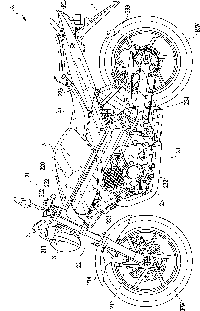
[0046] First, see figure 2 Shown is a schematic side view of the motorcycle of the present invention. The motorcycle 2 includes a steering mechanism 21, a frame unit 22, a power unit 23, a fuel tank 24, a driver's seat 25, and the like.

[0047] The steering mechanism 21 is mainly to set a steering handle 212 above the steering head pipe 211, and to fix a large lamp 3 in front of the steering head pipe 211. An instrument 5 is arranged above the headlight 3. A front shock absorber 213 is connected to the bottom, and the bottom of the front shock absorber 213 is supported by a front wheel FW, and a front soil removal 214 is arranged between the steering head pipe 211 and the front wheel FW.

[0048] The vehicle frame unit 22 has a main pipe 220 extended from the top of the steering head pipe 2...


PUM


Abstract

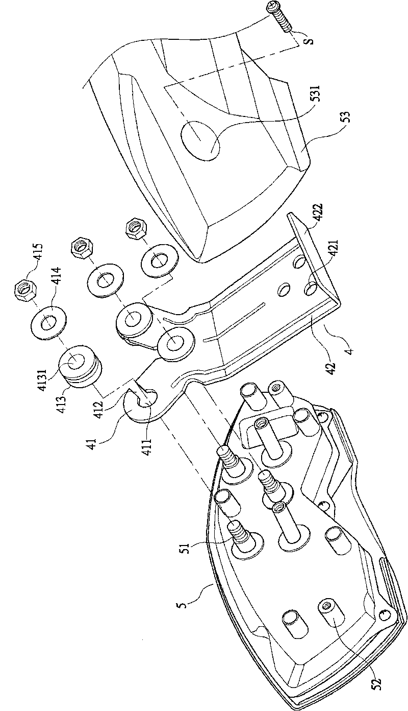
The invention relates to a connection structure of a console and a headlamp, which at least comprises the console, a supporting element and the headlamp. The console is convexly provided with a plurality of fixed studs. The upper part of the supporting element is provided with a first fixed end. The first fixed end is provided with a plurality of fixed holes corresponding to the fixed studs. The fixed holes can be used for the fixed studs to be inserted in and fixed by screw caps. The lower part of the supporting element is provided with a second fixed end. The second fixed end is provided with a plurality of connection holes. A bending pressing part is arranged below the connection holes. The headlamp is provided with a fixed seat. The fixed seat is convexly provided with a plurality of studs corresponding to the connection holes of the supporting element. The outside of the headlamp is provided with a plurality of combination holes which can be locked with a frame. The supporting element is locked between the console and the headlamp so as to make the headlamp and the console modularized, and the modularized headlamp is fixedly arranged on the frame to achieve the aim of simplifying the installation engineering.

Description

【Technical field】 [0001] The present invention relates to a connection structure between an instrument and a headlight, in particular to a connection mechanism which can simplify the installation project and avoid damage to the internal components of the instrument due to vibration when the vehicle is running. 【Background technique】 [0002] All kinds of motorcycles have been widely used by the public, and have become a short-distance means of transportation that consumers often use in their daily lives, and each car factory exports a large number of motorcycles to foreign markets every year, which contributes to the local economy. The improvement of strength has made a great contribution; as far as transportation is concerned, in addition to mass public transportation such as MRT and public buses, there are also a large number of personal transportation, such as cars and motorcycles, among which motorcycles The convenient and fast functions are unmatched by other means of t...

Claims


Application Information

Patent Timeline
IPC IPC(8): B62J6/02B62J99/00
Inventor 涂世旺
Owner KYMCO
Learn More