Supercharge Your Innovation With Domain-Expert AI Agents!

Spar edge strip system of wind turbine rotor blade and method for manufacturing rotor blade

A technology for wind turbines and rotor blades, which is applied in the field of spar cap systems, and can solve the problems of rotor blades such as heavy strength, high cost, and high design cost

Inactive Publication Date: 2010-06-23
GENERAL ELECTRIC CO
View PDF6 Cites 13 Cited by
  • Summary
  • Abstract
  • Description
  • Claims
  • Application Information

AI Technical Summary

Problems solved by technology

Stiffness requirements met by glass sparcaps make rotor blades too heavy and too strong, while carbon sparcaps result in lightweight but too stiff rotor blades
Carbon sparcaps are advantageous due to high stiffness and low density, but on the other hand, carbon sparcaps are more expensive compared to glass sparcaps
So conventional blade designs are either too strong which makes the design too heavy or too stiff which makes the design expensive

Method used


Image

  • Spar edge strip system of wind turbine rotor blade and method for manufacturing rotor blade
  • Spar edge strip system of wind turbine rotor blade and method for manufacturing rotor blade
  • Spar edge strip system of wind turbine rotor blade and method for manufacturing rotor blade

Examples


Embodiment Construction

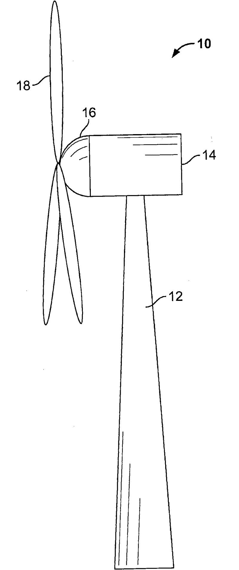
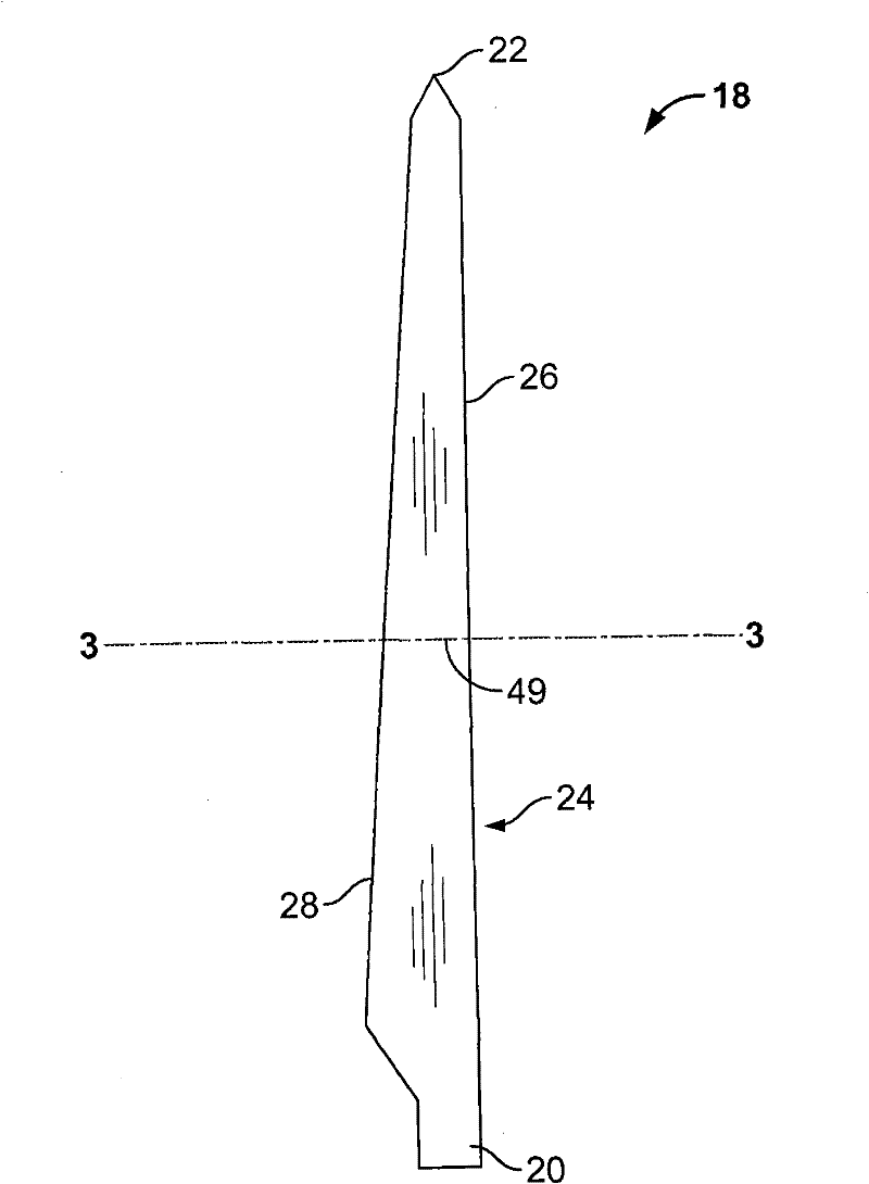
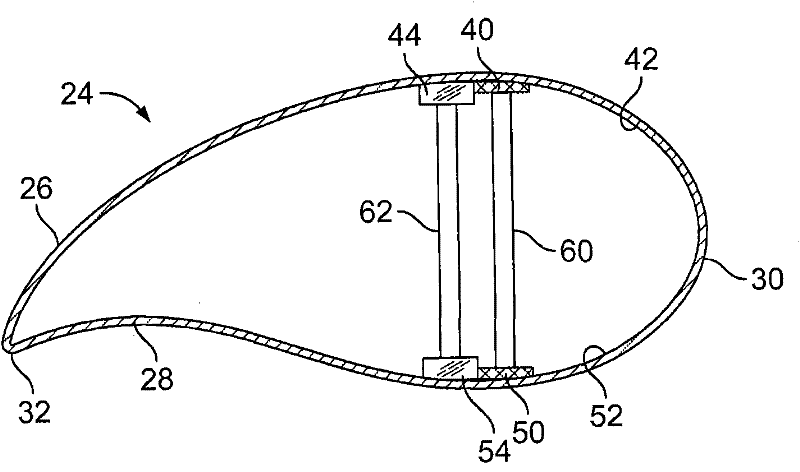
[0039] Embodiments described herein provide a rotor blade for a wind turbine comprising a sparcap system adapted to provide sufficient strength to the rotor blade while reducing the overall weight and / or manufacturing costs of the rotor blade. The sparcap system includes a first sparcap and a second sparcap, the first sparcap comprising a carbon material positioned on and coupled to an inner surface of the rotor blade first blade section, A second sparcap comprising a glass material is positioned adjacent to the first sparcap and coupled to the first blade section and is positioned forward relative to the first sparcap along the cross-sectional width of the rotor blade. edge direction or trailing edge direction. The use of a first sparcap comprising a carbon material and a second sparcap comprising a glass material adjacent to the first sparcap allows for the manufacture of longer and / or larger rotor blades while reducing the The spar cap mass and blade static moment, which c...


PUM


Abstract

The invention relates to a spar edge strip system of a wind turbine rotor blade and a method for manufacturing the rotor blade and particularly provides the rotor blade (18) of the wind turbine (10). The rotor blade (18) comprises a first blade section (26), a second blade section (28) which is formed by being connected to the first blade section, a first spar edge strip (40) and a second spar edge strip (44), wherein a front edge (30) and a back edge (32) are both arranged on the first and second blade sections; the first spar edge strip (40) contains a carbon material (70) and is positioned on the inner surface (42) of the first blade section; the second spar edge strip (44) contains a glass material (72) and is positioned on the first blade section; and the second spar edge strip is positioned on the direction of the front edge or the back edge opposite to the first spar edge strip.

Description

technical field [0001] Embodiments described herein relate generally to wind turbine rotor blades, and more particularly to sparcap systems for wind turbine rotor blades. Background technique [0002] Wind turbine blades generally comprise two blade shells formed of fiber reinforced polymer. The blade shells are molded and then joined together along mating edges using a suitable adhesive material. At least some turbine blades include one or more supports adhesively coupled to an inner surface of the first blade shell portion. The cooperating second blade shell part is then arranged on top of the brace and is adhesively coupled to the first blade shell part along its edge. [0003] Blade shells are usually produced in mouldings, using suitable layers of evenly distributed fibres, fiber bundles or fiber mats. However, the blade shell is relatively light and has only low rigidity. Consequently, the stiffness and rigidity and buckling strength of the blade shell may not with...

Claims


Application Information

Patent Timeline
Patent Type & Authority Applications(China)
IPC IPC(8): F03D1/06
CPCF03D1/0683F03D1/0675B29L2031/085Y02E10/72F05B2240/301Y02E10/721Y10T29/49337Y02P70/50
Inventor A·阿克赫塔
Owner GENERAL ELECTRIC CO
Features
  • R&D
  • Intellectual Property
  • Life Sciences
  • Materials
  • Tech Scout
  • Unparalleled Data Quality
  • Higher Quality Content
  • 60% Fewer Hallucinations
Learn More