Airflow generating method and device

A production method and production device technology, which can be applied to machines/engines, non-displacement pumps, mechanical equipment, etc., can solve the problems of multiple desktops, loud noise, inconvenient cleaning, etc., to reduce the occupied area, good safety, and easy to clean. Effect

Inactive Publication Date: 2010-06-23
HANGZHOU DEEP ICE TECH +1
View PDF0 Cites 115 Cited by
  • Summary
  • Abstract
  • Description
  • Claims
  • Application Information

AI Technical Summary

Problems solved by technology

[0005] 1. Inconvenient to clean
[0006] For ceiling fans hanging on the roof, the dust contaminated on the blades needs to be climbed up to be cleaned, which is very inconvenient
For floor fans, rotary fans, and table fans, it is inconvenient to remove the protective cover, especially if the blades are contaminated with dust and cleaned.
[0007] 2. Poor security
The base of the table fan is more than 30cm long, which takes up more space on the desktop an...

Method used


Image

  • Airflow generating method and device
  • Airflow generating method and device
  • Airflow generating method and device

Examples


Embodiment 1

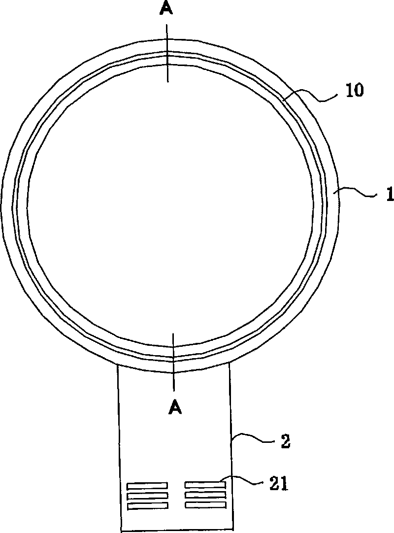
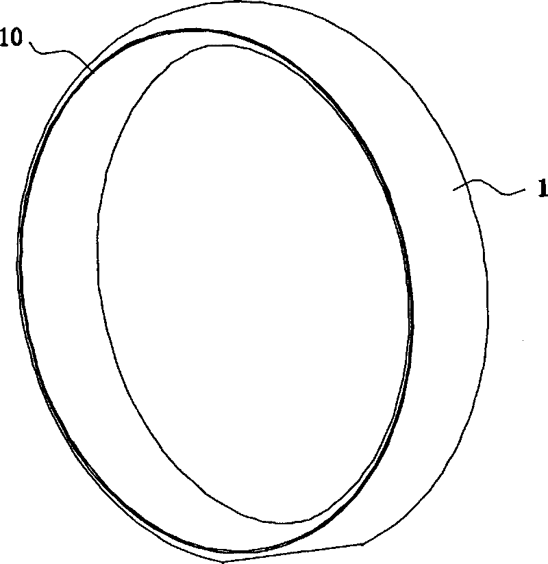
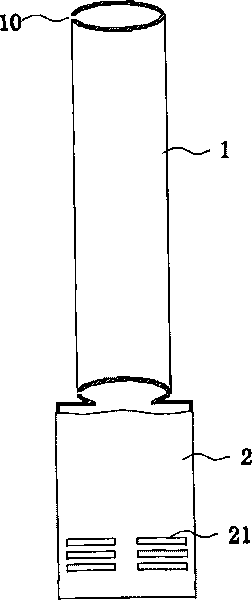
[0061] Such as figure 1 As shown, a device for generating airflow is applied in a fan, and the device includes an airflow generating unit 2 and a nozzle 1 .

[0062] Such as figure 1 , 3 As shown, the airflow generating unit 2 includes a housing, a motor, an impeller, and a diffuser, and an air inlet 21 is arranged on the housing. The motor adopts a DC motor, and the impeller is installed on the rotating shaft of the motor. The diffuser is located downstream of the impeller and consists of a fixed static disc with helical blades.

[0063] The inlet leading to the impeller communicates with the air inlet 21 . The outlet of the diffuser and the exhaust port of the impeller communicate with the hollow passage or duct in the housing to generate the airflow from the impeller to the inner passage of the nozzle. The motor is controlled by the controller, and the cooperation of the controller and a plurality of selection buttons enables the user to control the fan.

[0064] Such...

Embodiment 2

[0072] A device for generating airflow applied in a fan, which differs from Embodiment 1 in that:

[0073] 1. The nozzle is in the shape of a ring as a whole, and the diameter of the ring is 300mm;

[0074] 2. The relationship between the area A of the exhaust port and the air volume Q produced by the device is: Q 1015 A Q 54 , The air volume Q required by the device is [0.3m 3 / s, 1.1m 3 / s], choose 0.002m for area A 2 , the distance between the opposing surfaces used to form the vent is 2mm.

[0075] During the use of the above-mentioned device, the gauge pressure of the airflow in the internal channel is adjusted, such as from 200Pa to 1500Pa, so that the requirement of the air volume Q can be met.

[0076] A method for generating airflow applied in a fan, which is different from Embodiment 1 in that:

[0077] 1. The nozzle is in the shape of a ring as a whole, and the d...

Embodiment 3

[0086] A device for generating airflow applied in a fan, which differs from Embodiment 2 in that:

[0087] The relationship between the area A of the exhaust port and the air volume Q produced by the device is: Q 857 A Q 54 , The air volume Q required by the device is Area A selects 0.0004m 2 , the distance between the opposing surfaces used to form the vent is 0.4mm.

[0088] During the use of the above-mentioned device, the gauge pressure of the airflow in the inner channel is adjusted, such as from 300Pa to 2000Pa, so that the requirement of the air volume Q can be met.

[0089] A method for generating airflow applied in a fan, different from Embodiment 2 in that:

[0090] Keep the gauge pressure of the gas in the internal channel constant, for example, 300Pa, and adjust the distance between the opposite surfaces used to form the exhaust port from 0.2mm to 2mm. Please ref...


PUM


Abstract

The invention discloses an airflow generating method which comprises the following steps: an airflow generating unit and a nozzle are provided, wherein the nozzle is provided with an inner passage and a vent port, and the inner passage is communicated with the interior of the airflow generating unit; the airflow provided by the airflow generating unit is introduced into the inner passage, and thegage pressure of the airflow in the inner passage is 50-5000 Pa; the airflow in the inner passage is discharged from the vent port, and the discharged air does not produce the Coanda effect on the nozzle and entrains the air around the vent port, thereby amplifying the airflow. The invention also discloses an airflow generating device by using the method. The invention has the advantages of easy cleaning, high safety, high efficiency, small size, no effect on light rays, low noise and the like, and can be widely used in various fan units.

Description

technical field [0001] The invention relates to gas flow, in particular to a method and device for generating air flow. Background technique [0002] Due to the advantages of energy saving and low cost, fans have been widely used. At present, there are many types of fans available in the market, such as ceiling fans, floor fans, rotary fans, air-conditioning fans, etc. In recent years, fans with sterilization, deodorization and negative ion purification functions have also appeared. [0003] The basic components of the existing electric fan are: a driving device with a rotating shaft, such as an AC or DC motor, blades or wings of various shapes are installed on the rotating shaft, and a speed regulating device for adjusting the average rotational speed of the driving device. And in the fans such as floor fan and leaf fan except the ceiling fan, protective covers are also installed to prevent people, animals or objects from touching the rotating blades or wings and causing a...

Claims


Application Information

Patent Timeline
IPC IPC(8): F04F5/16
Inventor 李增珍孙敬文
Owner HANGZHOU DEEP ICE TECH
Why Eureka
Try Eureka