Explosion venting bolt fastener for pressure relief facility

A technology of bolt fasteners and explosion venting, which is applied in the direction of mechanical equipment, engine components, and functional valve types, etc., can solve the problems of not having self-tapping heads, rusting of explosion venting bolt fasteners, and the thickness should not be too thick. Achieve the effects of avoiding chemical corrosion and rust, reducing installation workload, and strengthening waterproof effect

Inactive Publication Date: 2010-06-23
李宝龄
View PDF0 Cites 21 Cited by
  • Summary
  • Abstract
  • Description
  • Claims
  • Application Information

AI Technical Summary

Problems solved by technology

However, the use of light walls as pressure relief facilities cannot ensure that the pressure in the factory building can be released to the outside in time during the explosion, and the factory building will collapse, which will cause significant personnel and property losses.
[0003] Existing explosion-venting bolt fasteners generally include a bolt and a metal washer, wherein the metal washer is a flat metal washer, and the thickness of the washer must have certain fragility in consideration of the explosion-venting effect, so the thickness cannot Too thick, but at the same time must meet the function of the external wall bolt fasteners, but when installing the existing explosion-venting bolts, the flat metal gasket is often damaged due to excessive force
In addition, due to the uncertainty of the external environment, the function of the explosion-venting bolt fasteners will be affected. For example, the explosion-venting environment is mostly an area where chemicals are stored, and corrosive gases are likely to volatilize in the air, which may easily cause the explosion-venting bolt fasteners to be damaged. Rust, and then the explosion-venting bolt fasteners are prone to breakage under certain negative wind pressure, such as typhoon season
In addition, the existing bolts do not have self-tapping heads, so they must be drilled with a pistol before installation, and then manually locked and fixed on the pressure relief facility, which increases the difficulty and man-hours of construction and installation.

Method used


Image

  • Explosion venting bolt fastener for pressure relief facility
  • Explosion venting bolt fastener for pressure relief facility
  • Explosion venting bolt fastener for pressure relief facility

Examples


Embodiment Construction

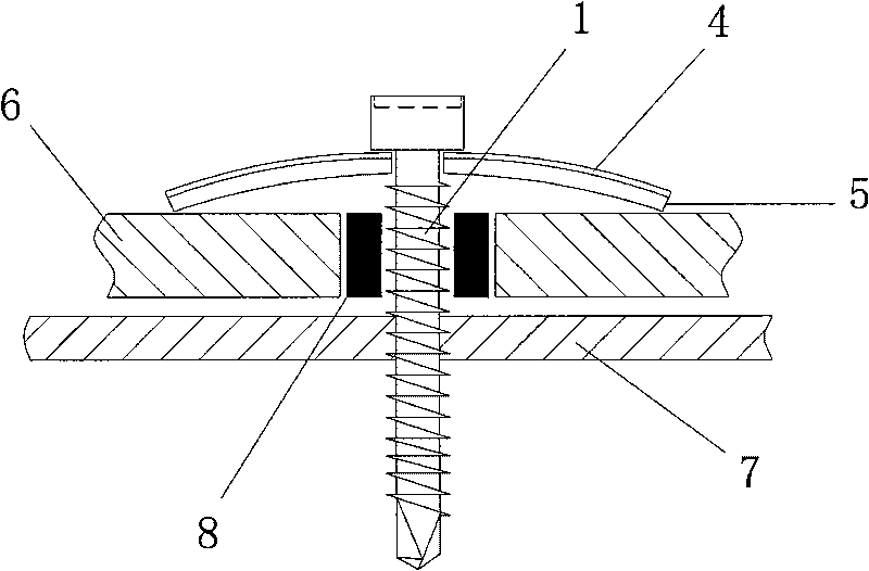
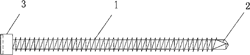
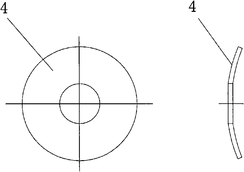
[0022] Such as figure 1 As shown, before the explosion occurs, the explosion-venting bolt fastener 20 is in a non-working state. It can be seen that the explosion-venting bolt fastener 20 is composed of a metal gasket 4 , a screw rod 1 and an elastic gasket 5 . Before installation, a hole is first opened on the outer wall panel 6 for the screw rod 1 to pass through, and then the fastener, the outer wall panel 6 and the structural wall beam 7 are matched and installed in sequence. During this process, because the end of the screw rod 1 has a self-tapping head 2, the self-tapping function can be realized. In addition, there is a rubber sleeve 8 between the screw rod 1 and the outer wall panel 6 to strengthen the cooperation between the two. Elastic washer 5 (this elastic washer also adopts rubber, also can other material) is attached to the below of metal washer 4 according to this radian, and elastic washer 5 preferably EPDM layer. The arc angle combination of the metal gask...


PUM


Abstract

The invention discloses an explosion venting bolt fastener for a pressure relief facility, which can strengthen the strength of the explosion venting bolt fastener without increasing the thickness and also strengthen the waterproof effect of the explosion venting bolt fastener. The explosion venting bolt fastener comprises a screw rod and a metal spacer sleeved at the head part of the screw rod. An elastic spacer which is sleeved on the screw rod is also arranged below the metal spacer, and the metal spacer is in an arc structure protruding outwards; the elastic spacer is in the same arc structure with the metal spacer and clings below the metal spacer; the arc structure can adopt a spherical surface structure, the elastic spacer can adopt a rubber spacer; a tapping head is arranged at the end of the screw rod; and a corrosion and rust resistance layer is plated on the threaded surface of the screw rod.

Description

technical field [0001] The invention relates to an explosion-venting bolt fastener, in particular to an explosion-venting bolt fastener capable of realizing pressure relief according to quantified explosion-venting pressure. Background technique [0002] The Code for Fire Protection Design of Buildings (GB50016-2006) requires that Class A and Class B factory buildings and boiler rooms with explosion hazards should be equipped with pressure relief facilities. However, there is no explanation on how to quantify the explosion pressure of the pressure relief facilities, and the domestic practice only uses light walls as pressure relief facilities. However, using a light wall as a pressure relief facility cannot guarantee that the pressure in the factory building can be released to the outside in time during the explosion, and the factory building will collapse, which will cause significant personnel and property losses. [0003] Existing explosion-venting bolt fasteners general...

Claims


Application Information

Patent Timeline
Patent Type & Authority Applications(China)
IPC IPC(8): F16K17/14F16K27/00E04H9/00
Inventor 李宝龄
Owner 李宝龄
Why Eureka
Try Eureka