Two-dimensional correction method for closing error of stacking velocity and root-mean-square velocity field

A root-mean-square velocity and stacking velocity technology, which is applied in seismic signal processing and other directions, can solve the problems of reducing accuracy, accuracy limitation, reducing closure error and obtaining accuracy, etc.

CN101750628AActive Publication Date: 2010-06-23PETROCHINA CO LTD
0 Cites 19 Cited by

Patent Information

Authority / Receiving Office
CN · China
Current Assignee / Owner
Publication Date
2010-06-23

Smart Images

  • Figure 1
    Figure 1
  • Figure 2
    Figure 2
  • Figure 3
    Figure 3
Patent Text Reader

Abstract

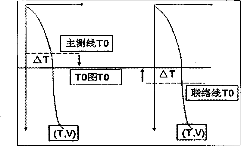
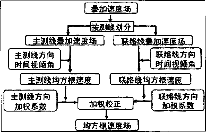
The invention relates to a two-dimensional two-step correction method of a stacking velocity and a root-mean-square velocity field, which comprises the steps of: firstly, acquiring the time difference delta T of each measuring line before correcting a T0 curve surface and a T0 in a closing way; correcting the stacking velocity with the delta T on reference plane, wherein when the delta T is larger than 0, a correction velocity uses a ground surface filling velocity, and when the delta T is less than 0, the correction velocity uses a velocity on a velocity spectrum; and aiming at the root-mean-square velocity closing error caused by apparent dip when the stacking velocity is converted into the root-mean-square velocity, firstly obtaining the time gradient of the stacking profile of a main measuring line and a communication measuring line, acquiring the apparent dip and the root-mean-square velocity of the directions of the different measuring lines, calculating the weighting coefficient at the point of intersection, interpolating and normalizing the weighting coefficient at the point of intersection, and stacking the root-mean-square velocity of the main measuring line and the communication line in a weighting way to obtain a final root-mean-square velocity field with the weighting coefficient of the directions of the different measuring lines. The method scientifically and effectively eliminates the closing error of the velocity of the intersected measuring lines, and improves the precision of the velocity field of a two-dimensional earthquake work area.
Need to check novelty before this filing date? Find Prior Art

Description

Technical field:

[0001] The invention relates to a method for correcting superposition velocity and root mean square velocity field accuracy of two-dimensional seismic work area velocity field construction in low-amplitude structural trap petroleum seismic exploration. Background technique:

[0002] In the data interpretation and variable-velocity mapping work in the 2D seismic work area, there are generally problems of time and velocity field closure gaps in the reflection layer at the intersection points of the survey lines. At present, the research on the time closure problem of the reflective layer at the intersection of survey lines is relatively in-depth, but the research on the velocity field closure problem is still rare. More representative ones are Zuo Longping et al. who proposed in 2000 to calculate the correction operator for different survey lines, and perform time-varying and space-varying time difference correction and waveform correction on the intersection ...

Examples

Embodiment 1

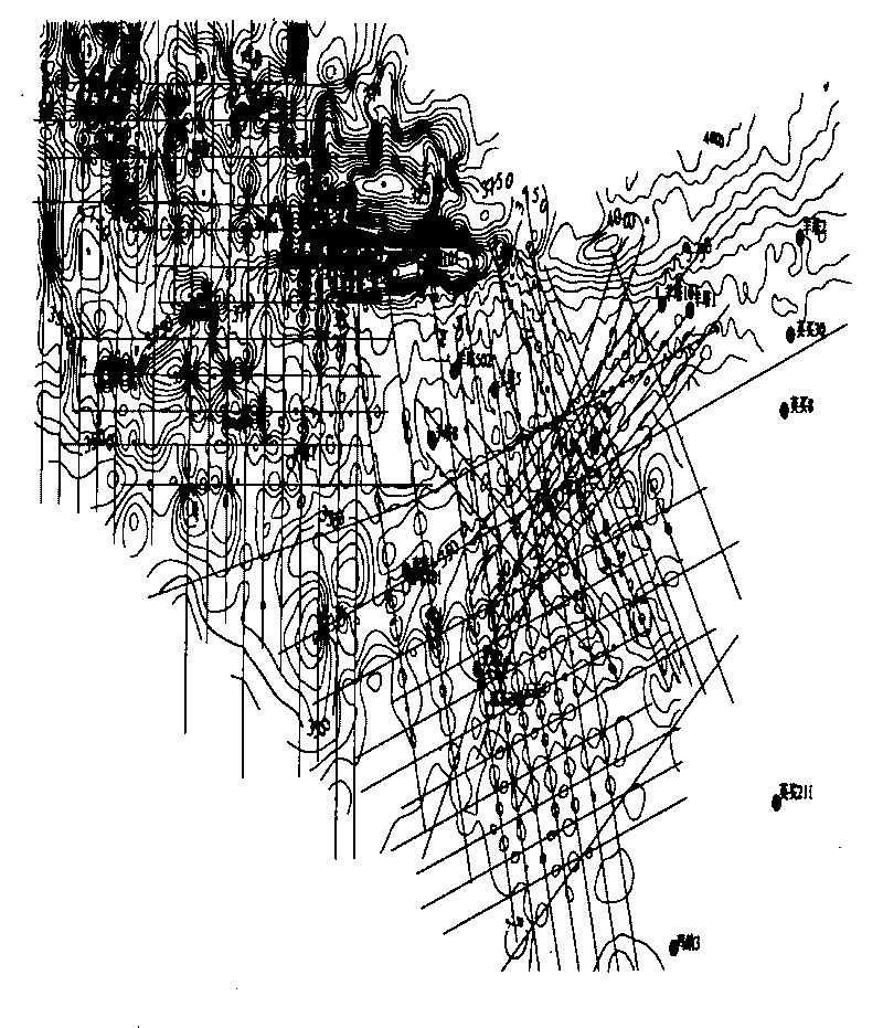
[0046]In a 2D seismic work area, the exploration target layer is deeply buried, and the structural fluctuations are relatively gentle, so the accuracy of the seismic velocity field is relatively high. The original seismic data in the work area have a large velocity closure difference ( image 3 ), it needs to be corrected to improve the accuracy of the seismic velocity field.

[0047] 1. T 0 Correction of superimposed velocity misclosure caused by misclosure

[0048] ①T 0 Calculation of closure difference

[0049] Firstly, the seismic interpretation data of the whole work area are processed by T 0 Grid interpolation is performed after closure error correction to form the seismic interpretation of the entire work area, etc. 0 Figure, with T 0 The surface file of the graph subtracts each seismic line without doing T 0 The scatter point data corrected by the closure difference is used to obtain the ΔT scatter point data distributed along the seismic survey line.

[0050] ...

Embodiment 2

[0080] The surface and underground geological structure of the B work area is complex, the two-dimensional seismic survey network is 2×4~4×4km, there are factors such as different construction years and different processing units, and the problem of cross-survey velocity closure is serious ( Image 6 ), the focus of variable-speed mapping is to do a good job of correcting the closure difference. Use the following calibration steps:

[0081] 1. T 0 Correction of superimposed velocity misclosure caused by misclosure

[0082] The area T 0 The closing difference is 20-45ms, and the speed closing difference caused by it cannot be ignored and must be corrected.

[0083] ①T 0 Calculation of closure difference

[0084] Firstly, the seismic interpretation data of the whole work area are processed by T 0 Grid interpolation is performed after closure error correction to form the seismic interpretation of the entire work area, etc. 0 Figure, with T 0 The surface file of the graph ...