Monitoring system for environment simulation

A monitoring system and environment simulation technology, applied in the direction of comprehensive factory control, comprehensive factory control, electrical program control, etc., to achieve the effect of rapid acceptance

Active Publication Date: 2012-12-12
GREE ELECTRIC APPLIANCES INC
View PDF1 Cites 0 Cited by
  • Summary
  • Abstract
  • Description
  • Claims
  • Application Information

AI Technical Summary

Problems solved by technology

[0005] Aiming at the defect that the above-mentioned existing monitoring system cannot monitor environmental parameters quickly and effectively, a monitoring device for laboratory use that can monitor environmental parameters quickly and effectively is provided. Specifically, the present invention provides a monitoring device for environmental simulation. The monitoring device includes an environmental parameter monitoring device for measuring environmental parameters, an environmental parameter control device for controlling environmental parameters, and a programmable logic controller (hereinafter referred to as PLC), which is used to receive the information of the environmental parameter monitoring device. Monitoring results and output switching values; a touch screen connected to the PLC for inputting control signals to the PLC; a control switch consisting of a relay and a contactor, the relay pulls the contactor according to the switching value output by the PLC, so The contactor is connected in series with the power supply circuit of the environmental parameter control device for controlling the start and stop of the environmental parameter control device

Method used


Image

  • Monitoring system for environment simulation
  • Monitoring system for environment simulation
  • Monitoring system for environment simulation

Examples


Embodiment Construction

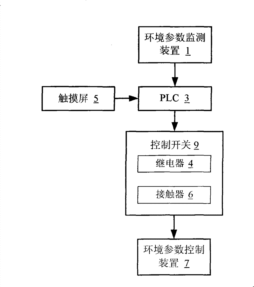
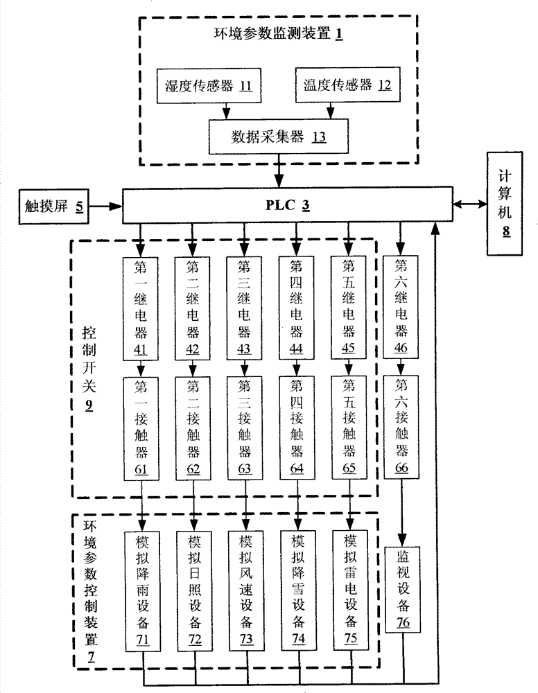
[0021] figure 1 is a block diagram of the monitoring system for environment simulation of the present invention, such as figure 1 As shown, the monitoring system includes an environmental parameter monitoring device 1 , a PLC 3 and its touch screen 5 , a control switch 9 and an environmental parameter control device 7 . Among them, the environmental parameter monitoring device 1 is used to measure environmental parameters; PLC 3 is an important control mechanism with receiving signal source, transmission switch value, and feedback analog parameters. PLC 3 is used to receive the monitoring results of environmental parameter monitoring device 1, and output Switching value, the output switching value is a small weak current; the touch screen 5 is connected to the PLC 3 for inputting control signals to the PLC 3; the control switch 9 is composed of a relay 4 and a contactor 6, and the relay 4 can output according to the PLC 3 The switch value pulls the contactor 6, and the contac...


PUM


Abstract

The invention provides a monitoring system for environment simulation, comprising: an environment parameter monitoring device (1), an environment parameter controller (7), a programmable logic controller PLC (3), a touch screen (5) and a control switch (9), wherein the environment parameter monitoring device (1) is used for monitoring environment parameters; the environment parameter controller (7) is used for controlling the environment parameters; the programmable logic controller PLC (3) is used for receiving monitoring results of the environment parameter monitoring device (1) and the switch quantity output; the touch screen (5) is connected with the PLC (3) for inputting control signals to the PLC (3); the control switch (9) consists of a relay (4) ad a contactor (6), the relay (4) closes the contactor (6) according to the switching valve output by the PLC (3) in an attracting manner, and the contactor (6) is connected with a power supply circuit of the environment parameter controller (7) in series and is used for controlling the starting and the stopping of the environment parameter controller (7). The monitoring system can rapidly receive signals, process signals, and output the switching value and the like so as to achieve the simulation of outside environment by adopting the PLC and the touch screen.

Description

technical field [0001] The present invention relates to a monitoring system, more particularly, to a monitoring system for an environment module. Background technique [0002] The monitoring system has been widely used in various fields. The function of the monitoring system in the public domain is to ensure the safety of personnel, numerous property facilities and important data. The monitoring system in the industrial field can be used to monitor and control the entire production process or production process, collection, analysis, processing Relevant data realizes the automation and intelligent operation of the production system. [0003] The monitoring device can also be used in the simulated environment research laboratory to simulate various indoor and outdoor natural environments. By changing various meteorological factors, the air conditioner installed in the simulated living room can be adjusted for comfort, energy saving, and reliability. The test and experiment, ...

Claims


Application Information

Patent Timeline
Patent Type & Authority Patents(China)
IPC IPC(8): G05B19/418G01W1/02
CPCY02P90/02
Inventor 张辉王彤肖彪董术海吕剑明丁洪斌
Owner GREE ELECTRIC APPLIANCES INC
Why Eureka
Try Eureka