Vacuum vessel, vacuum vessel manufacturing method, vacuum processing apparatus, and electronic device manufacturing method

A vacuum container and container technology, applied in semiconductor/solid-state device manufacturing, electrical components, mechanical equipment, etc., can solve the problems of vacuum performance reliability degradation, increase manufacturing cost, etc., and achieve reduced manufacturing cost, simple structure, and easy vacuum container. Effect

Active Publication Date: 2010-06-23
CANON ANELVA CORP
View PDF9 Cites 2 Cited by
  • Summary
  • Abstract
  • Description
  • Claims
  • Application Information

AI Technical Summary

Problems solved by technology

This is problematic due to the ensuing increase in manufacturing costs and degraded reliability of vacuum performance

Method used


Image

  • Vacuum vessel, vacuum vessel manufacturing method, vacuum processing apparatus, and electronic device manufacturing method
  • Vacuum vessel, vacuum vessel manufacturing method, vacuum processing apparatus, and electronic device manufacturing method
  • Vacuum vessel, vacuum vessel manufacturing method, vacuum processing apparatus, and electronic device manufacturing method

Examples


Embodiment Construction

[0039] Detailed embodiments of the present invention will be described below with reference to the accompanying drawings.

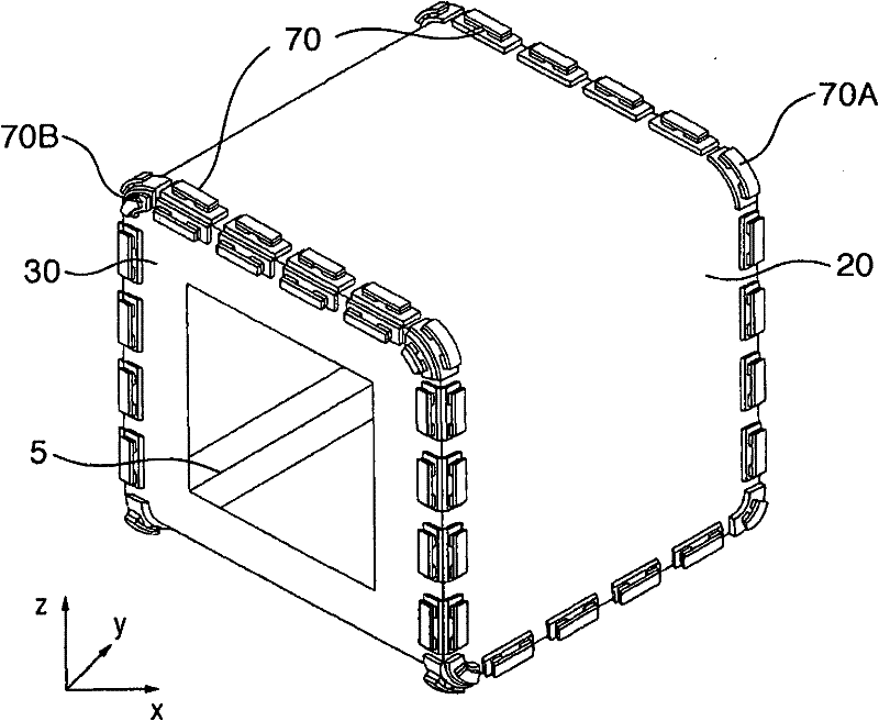
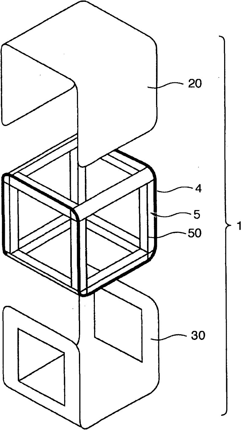
[0040] figure 1 A vacuum container according to one embodiment of the present invention is shown. This example will illustrate a hexahedral vacuum vessel. figure 2 yes figure 1 An exploded perspective view of the vacuum vessel shown in .

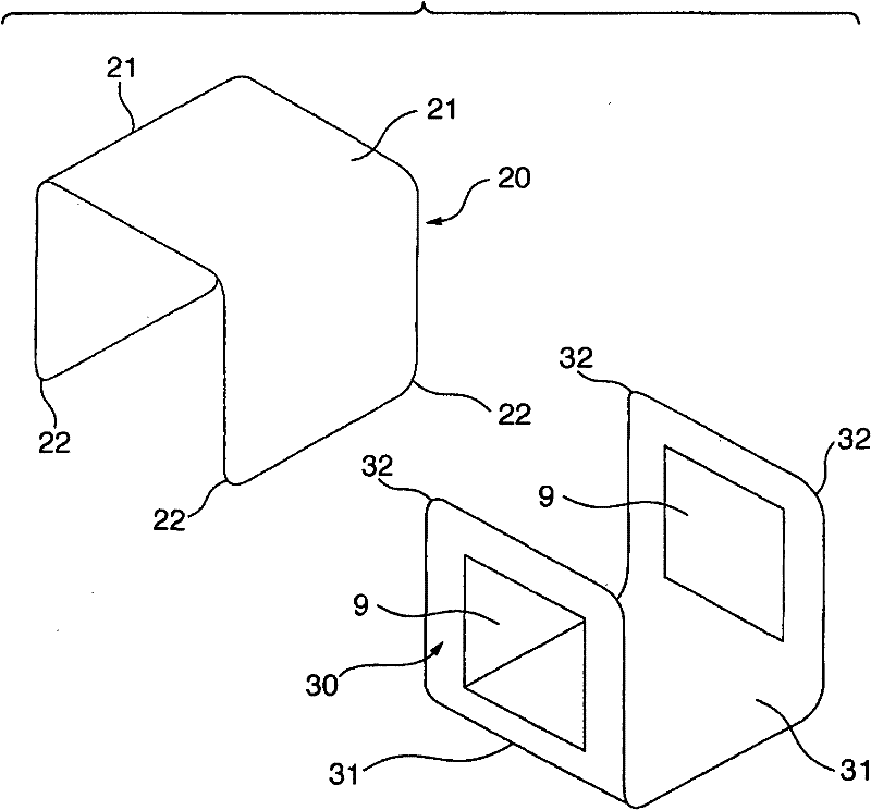
[0041] Such as figure 1 with2 As shown in , the vacuum container 1 includes a pair of curved members 20 and 30 . The bending members 20 and 30 are formed by bending a metal plate into a predetermined shape. The vacuum vessel 1 is formed by combining the curved members 20 and 30 with each other to form a closed space inside the curved members 20 and 30 . The vacuum vessel 1 also includes a sealing member 4 and a cubic lattice structure 5 . The sealing member 4 seals the gap in the joint portion between the bent members 20 and 30 . The structure 5 is housed in the closed space while abutting against the inner ...


PUM

PropertyMeasurementUnit
thicknessaaaaaaaaaa

Abstract

A vacuum vessel includes a pair of bending members which are formed by bending metal plates in predetermined shapes and are bonded to each other to form a closed space inside them. The vacuum vessel also includes a sealing member which seals the gap in the bonding portion between the bending members, and a cubic lattice structure which abuts against the inner surfaces of both the bending members and is accommodated in the closed space. The vacuum vessel further includes a magnet unit. The magnet unit fixes the bending members onto the structure and seals the gap in the bonding portion between the bending members by pressing an O-ring serving as a sealing member along the bonding portion.

Description

technical field [0001] The present invention relates to a vacuum container such as a process chamber or a transfer chamber, which constitutes a vacuum processing apparatus for processing, for example, a liquid crystal display substrate and a semiconductor wafer, and to a vacuum processing apparatus including the vacuum container, a vacuum container manufacturing method and method of manufacturing an electronic device. Background technique [0002] Processes such as thin film formation on, for example, liquid crystal display substrates and semiconductor wafers, and dry etching and heating of the formed thin films are mainly performed in a vacuum. Alignment, transport and the like, which prepare the processing objects for processing in a vacuum, are often also carried out continuously in a vacuum. In order to perform these processes, a vacuum processing apparatus formed by connecting a plurality of vacuum containers via gate valves is generally used (Japanese Patent Laid-Open...

Claims


Application Information

Patent Timeline
Patent Type & Authority Applications(China)
IPC IPC(8): H01L21/00B23P15/00
CPCH01L21/6719F16J15/062H01L21/67126Y10T29/49826
Inventor 佐佐木雅夫
Owner CANON ANELVA CORP
Why Eureka
Try Eureka