Novel latex sponge shaping device

A sizing device and latex technology, applied in the field of new latex sponge sizing device, can solve the problems affecting material comfort and performance, general heating effect, inability to penetrate latex, etc., to increase the stability of connection and installation, and improve the overall stability , Increase resilience and comfort

Inactive Publication Date: 2018-06-22
赵水均
View PDF0 Cites 0 Cited by
  • Summary
  • Abstract
  • Description
  • Claims
  • Application Information

AI Technical Summary

Problems solved by technology

[0002] The traditional way of shaping latex sponge is to use general high-temperature quartz tube to heat. The heating effect is average. It can only form a thin film on the surface of the latex, but cannot penetrate into the interior of the latex.
In the process of mechanical foaming of latex, the foam produced has a certain time limit. Over this period of time, the foam will automatically burst, so the traditional quartz tube heating method cannot shape the latex material internally, and the latex sheet produced , from the cross-section, the cell structure of the upper part and the lower part are inconsistent, the cells cannot be finalized, the cells of the material have been broken before vulcanization, and the cells of the material are thick after molding, which seriously affects the comfort and performance of the material. When injecting into the mold cavity, more or less some air will be left; these airs are attached to the bottom of the cavity and expand into air bubbles after being heated, which will bring defects to the shaped latex sponge, so it is necessary to carry out design improvement

Method used


Image

  • Novel latex sponge shaping device
  • Novel latex sponge shaping device

Examples


Embodiment Construction

[0018] In order to further understand the invention content, characteristics and effects of the present invention, the following embodiments are listed below, and detailed descriptions are as follows in conjunction with the accompanying drawings.

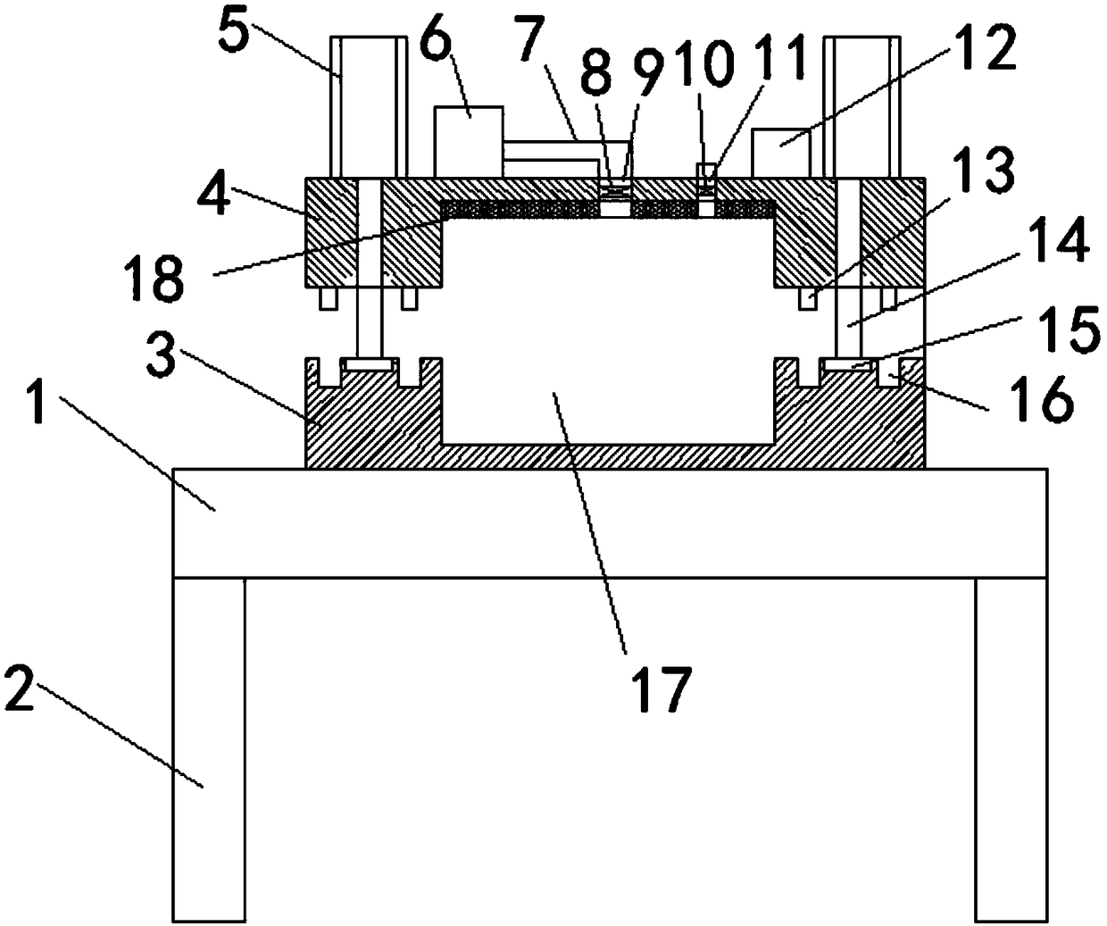
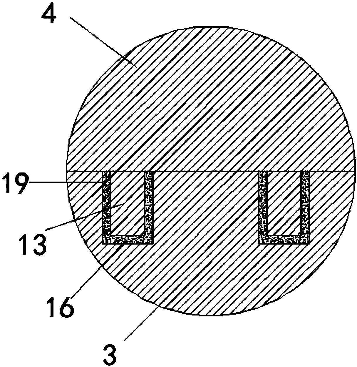
[0019] Combine below Figure 1-2 The novel latex sponge sizing device of the present invention is described in detail: a novel latex sponge sizing device, comprising a workbench 1, support legs 2, lower die 3 and upper die 4, is characterized in that, said support leg 2 is located at the working The four corners of the bottom surface of the table 1, the support legs 2 are embedded with the workbench 1, the upper surface of the workbench 1 is provided with a lower mold 3, the lower mold 3 and the workbench 1 are designed in an integrated manner, and the lower mold 3 Upper mold 4 is arranged above, and piston rod 14 is arranged between described lower mold 3 and upper mold 4, and the bottom end of described piston rod 14 is connected ...


PUM


Abstract

The invention relates to a novel latex sponge shaping device comprising a workbench, supporting legs, a lower mold and an upper mold. The supporting legs are arranged at four corners of the bottom surface of the workbench, the lower mold is fixedly connected to the upper surface of the workbench, and the upper mold is arranged above the lower mold. Air cylinders are arranged at the middle positions of the two sides of the upper surface of the upper mold, and the air cylinders are fixed to the upper surface of the lower mold through piston rods. According to the latex sponge shaping device, theupper mold and the lower mold are arranged, an infrared radiator is arranged in a cavity of the upper mold, and according to the design, due to the fact that the infrared radiator is large in power,good in radiation effect and capable of penetrating through the surface of a product and transferring heat into the product, foam holes are shaped before the foam in the product is broken, so that theinner foam holes of the product are uniform and dense, and the resilience and the comfort degree of the product are increased.

Description

technical field [0001] The invention belongs to the technical field of sponge shaping equipment, in particular to a novel latex sponge shaping device. Background technique [0002] The traditional way of setting latex sponge is to use ordinary high-temperature quartz tube to heat. The heating effect is average, and it can only form a thin film on the surface of the latex, but cannot penetrate into the interior of the latex. In the process of mechanical foaming of latex, the foam produced has a certain time limit. Over this period of time, the foam will automatically burst, so the traditional quartz tube heating method cannot shape the latex material internally, and the latex sheet produced , from the cross-section, the cell structure of the upper part and the lower part are inconsistent, the cells cannot be finalized, the cells of the material have been broken before vulcanization, and the cells of the material are thick after molding, which seriously affects the comfort and...

Claims


Application Information

Patent Timeline
Patent Type & Authority Applications(China)
IPC IPC(8): B29C67/20B29C33/06B29C33/10B29C33/30
CPCB29C67/20B29C33/06B29C33/10B29C33/30
Inventor 赵水均
Owner 赵水均
Why Eureka
Try Eureka