Power MOS pipe grid drive circuit and method for grid floating and level switching

A gate drive circuit and MOS tube technology, applied in the direction of output power conversion devices, electrical components, etc., can solve the problems of slow dynamic response, delay, and poor linearity of optocouplers, so as to prevent false conduction and reduce Energy loss, simple and reliable structure

Inactive Publication Date: 2010-06-23
SOUTHEAST UNIV
View PDF0 Cites 48 Cited by
  • Summary
  • Abstract
  • Description
  • Claims
  • Application Information

AI Technical Summary

Problems solved by technology

[0005] Using dedicated driver chips, such as IR2113, LM5100, etc., the cost is high and the circuit is complicated;
[0006] The use of isolation transformers requires winding transformers, which have problems such as large volume, delay, and saturation, and the driving waveform is not ideal at high frequencies;...

Method used


Image

  • Power MOS pipe grid drive circuit and method for grid floating and level switching
  • Power MOS pipe grid drive circuit and method for grid floating and level switching
  • Power MOS pipe grid drive circuit and method for grid floating and level switching

Examples


Embodiment Construction

[0025] The technical scheme of the invention will be described in detail below in conjunction with the drawings:

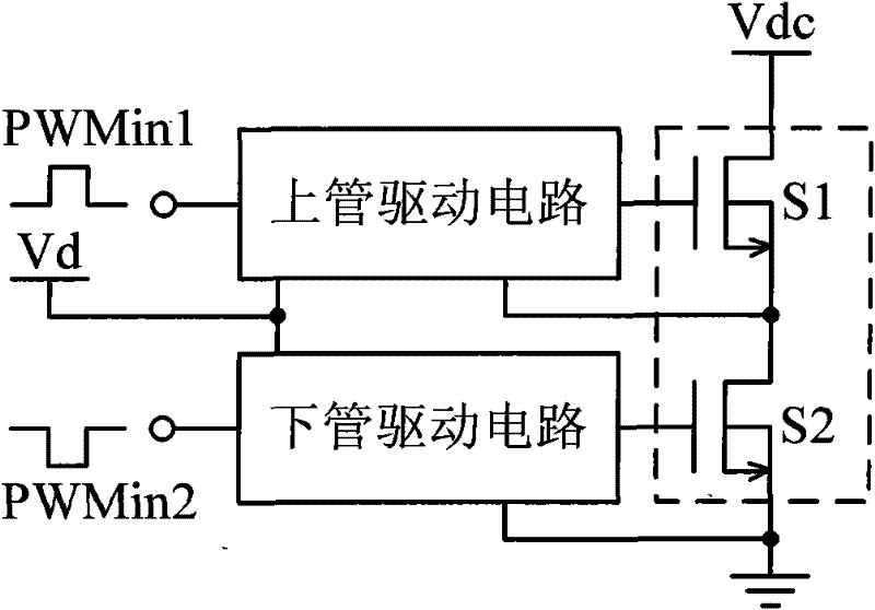
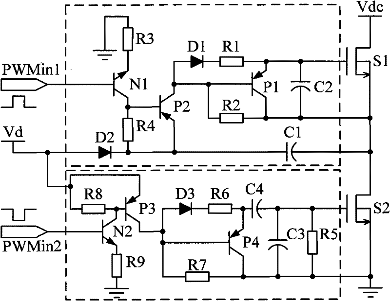
[0026] Such as figure 1 As shown, the gate driving circuit of the power MOS tube with floating gate and level conversion of the present invention includes an upper tube driving circuit and a lower tube driving circuit, characterized in that the upper tube driving circuit includes first to fourth resistors R1 ~R4, bootstrap capacitor C1, second capacitor C2, first and second diodes D1, D2, first and second PNP-type transistors P1, P2, and first NPN-type transistor N1, the lower tube driving circuit includes The fifth to ninth resistors R5 to R9, the third and fourth capacitors C3, C4, the third diode D3, the third and fourth PNP transistors P3, P4, and the second NPN transistor N2; the first NPN The base of the transistor N1 is connected to the first original pulse width modulation signal PWMin1, the emitter is connected to the third resistor R3 in series and then gro...


PUM


Abstract

The invention discloses a power MOS pipe grid drive circuit and method for grid floating and level switching. The drive circuit of the invention includes an upper pipe drive circuit and a lower pipe drive circuit, and is characterized in that the upper pipe drive circuit includes a first resistance, a second resistance, a third resistance and a fourth resistance, a bootstrap capacitance, a second capacitance, a first diode and a second diode, a first PNP type audion and a second PNP type audion, as well as a first NPN type audion; the lower pipe drive circuit includes a fifth resistance, a sixth resistance, a seventh resistance, an eighth resistance and a ninth resistance, a third capacitance and a fourth capacitance, a third diode, a third PNP type audion and a fourth PNP type audion as well as a second NPN type audion. The method can realize to convert grid drive level of upper and lower power MOS pipes, drive lower pipe grid and drive upper pipe grid floating. The invention does not adopt any drive chip, only consists of common discrete elements like resistance, capacitance and audion, etc, and has the advantages of low cost, high reliability and stability, as well as high drive efficiency.

Description

Technical field [0001] The invention relates to a power MOS tube gate driving circuit and method, in particular to a power MOS tube gate driving circuit and method with gate floating and level conversion functions. Background technique [0002] The driving structure of upper and lower power MOS tubes is widely used in many power converters today, such as half-bridge, full-bridge power supply, dual-tube forward power supply, inverter, motor drive, class D power amplifier, etc. The structure is such as figure 1 Shown in the dashed box. [0003] Generally, the gate drive of a power MOS tube requires a pulse width modulation signal with a high level of 10V to 15V, and a drive capability with an instantaneous current greater than 1A. In addition, for the gate drive of the upper tube, since the source potential is floating, the gate driving voltage must float on the source potential to drive the upper tube on normally. [0004] At present, in most power converter circuits, the original pu...

Claims


Application Information

Patent Timeline
IPC IPC(8): H02M1/08
Inventor 徐申何晓莹阚明建孙伟锋陆生礼时龙兴
Owner SOUTHEAST UNIV
Why Eureka
Try Eureka