Calibration method, calibration device, and calibration system having the device

A calibration method and camera system technology, which can be used in measuring devices, stereo systems, TV system components, etc., can solve problems such as damaged symmetry, inability to detect feature points, and difficulty in implementing high-precision calibration to achieve high precision The effect of calibration

Inactive Publication Date: 2010-06-23
PANASONIC CORP
View PDF3 Cites 18 Cited by
  • Summary
  • Abstract
  • Description
  • Claims
  • Application Information

AI Technical Summary

Problems solved by technology

therefore, Figure 12 In the compound eye distance measuring device shown, it is easy to generate a modeling error between the mathematical model of the camera and the actual camera during the inference calculation of the camera parameters described in Non-Patent Document 1, Patent Document 3, etc.
especially in Figure 12 In the compound eye distance measuring device shown, it is difficult to improve the distance measurement accuracy in the peripheral part of the image with large blur
[0065] ie, for example Figure 12 As shown in the compound eye distance measuring device of , in the calibration of a stereo distance measuring device that contains many lens aberrations in the image, even if the conventional feature point detection method is used, due to the large image aberration, there are problems as follows: interference The brightness of the image caused by it is reduced; if the deformation in the radial direction (sagittal direction) and its circumferential direction (tangential direction) are not considered, appropriate feature points cannot be detected; deformation in the image due to camera installation errors, etc. The symmetry (concentric circle) of the distribution relative to the position of the optical axis of the lens is impaired, which is prone to modeling errors between the mathematical model of the camera and the actual camera
As a result, high-precision feature point position detection cannot be performed, so it is difficult to implement high-precision calibration

Method used


Image

  • Calibration method, calibration device, and calibration system having the device
  • Calibration method, calibration device, and calibration system having the device
  • Calibration method, calibration device, and calibration system having the device

Examples


Embodiment approach 1

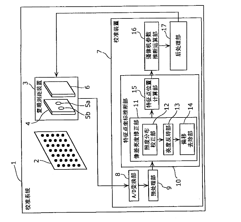
[0171] figure 1 It is a figure which shows the structure of the calibration system which concerns on this embodiment. As shown, the calibration system 1 has a reference figure 2 , compound eye ranging device 3 and calibration device 7. Hereinafter, each component and the overall processing flow of the calibration system 1 will be briefly described.

[0172] benchmark figure 2 It is a figure which draws the bead pattern of a black substantially circular element on a white background (white background) with a known size. Here, the bead pattern refers to a geometric pattern in which a plurality of elements forming a substantially circular shape are arranged. Additionally, the benchmark figure 2 The approximate center of gravity position (or approximate center position) of each element of , is assumed to be an actual feature point position, and the arrangement position of the feature point position is assumed to be known (produced with a known size). Furthermore, the app...

Embodiment approach 2

[0245] Next, Embodiment 2 of the present invention will be described with reference to the drawings.

[0246] Figure 9 It is a figure which shows the structure of the calibration system concerning this embodiment. And, with figure 1 Parts with the same numbers are subjected to the same processing as that in Embodiment 1, so description thereof will be omitted.

[0247] In addition, the calibration system 31 of this embodiment is different from the calibration system 1 of the embodiment in that the color matching of the reference chart 30 and the absence of the brightness inversion unit 13 in the calibration device 32, and other components and functions are the same as those of the first embodiment. Calibration system 1 is the same.

[0248] The reference diagram 30 is a diagram in which a bead pattern of white substantially circular elements is drawn on a black background (background black). That is, in the reference map 30 , the color of each element is a grayscale that...


PUM


Abstract

A high-accuracy calibration method for a range finder which captures an image involving much lens aberration. The calibration method is used for estimating the camera parameter representing the characteristic of each imaging system which a binocular range finer (3) has. The method includes an imaging step of imaging a reference chart (30) on which a geometric pattern composed of arranged elements is shown and which is disposed in a predetermined position relationship with a binocular range finder (3), an aberration brightness correcting step of correcting the brightness distribution due to the lens aberration in the captured image of the reference chart (30), a feature point position calculating step of calculating the positions of the centers of gravity of the elements shown in the image the brightness distribution of which is corrected as the feature point positions, and a camera parameter estimation calculating step of estimating a camera parameter by using the calculated feature point positions and the actual substantial centers of gravity of the reference chart (30).

Description

technical field [0001] The present invention relates to a calibration method, a calibration device, and the like of a distance measuring device capable of obtaining a distance to an object or a three-dimensional position or shape of the object. Background technique [0002] In recent years, there has been an increasing demand for a distance measuring device for measuring the distance from a predetermined position to an object or the three-dimensional position of the object, and further miniaturization of the measuring device is desired. For example, a distance measuring device constantly measures the position and shape information of passengers in the trunk of a car, and detects states that are dangerous during driving, such as distraction or dozing off. In addition, it has developed a safe driving assistance technology that issues a warning or applies the brakes to the car in advance according to the detected dangerous state. At this time, since the distance measuring devi...

Claims


Application Information

Patent Timeline
Patent Type & Authority Applications(China)
IPC IPC(8): G01C3/00H04N5/232G01C3/06H04N13/02H04N13/239
CPCH04N13/0246G01C3/14H04N2013/0081H04N13/0239H04N5/3572G01C25/00H04N13/246H04N13/239H04N25/61
Inventor 大山一朗今村典广
Owner PANASONIC CORP
Why Eureka
Try Eureka