Circuit board welding clamp

A welding fixture and circuit board technology, applied in welding equipment, auxiliary welding equipment, welding/cutting auxiliary equipment, etc., can solve problems such as incompetence for welding multiple circuit boards, and achieve improved welding accuracy, simple structure, and improved production efficiency. Effect

Inactive Publication Date: 2010-06-30
OCEANS KING LIGHTING SCI&TECH CO LTD +1
View PDF0 Cites 14 Cited by
  • Summary
  • Abstract
  • Description
  • Claims
  • Application Information

AI Technical Summary

Problems solved by technology

[0003] The technical problem to be solved by the present invention is to provide a circuit board welding fixture, which is convenient for welding the combination of multiple circuit boards, in view of the defect that the welding fixture in the prior art is not capable of welding after the combination of multiple circuit boards

Method used


Image

  • Circuit board welding clamp
  • Circuit board welding clamp
  • Circuit board welding clamp

Examples


Embodiment Construction

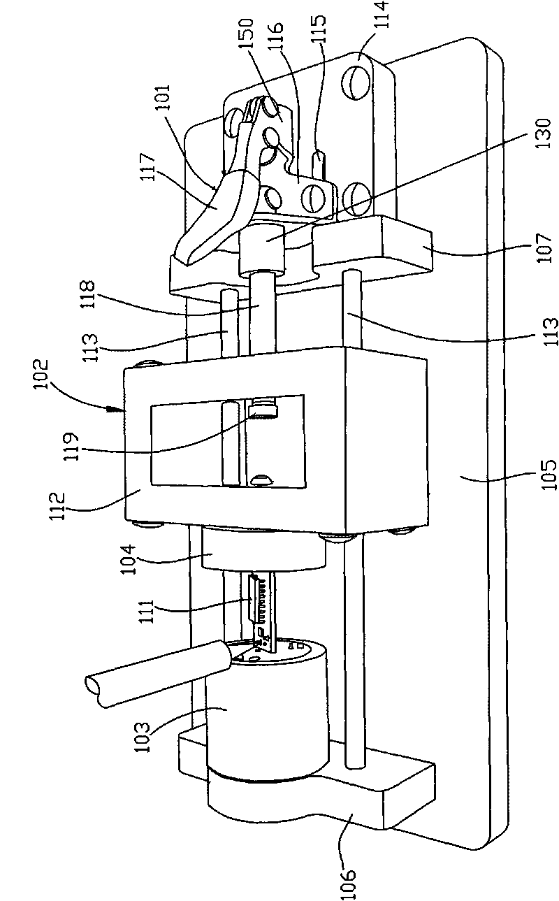
[0017] figure 1 It is a structural schematic diagram of the circuit board welding jig in the present invention. like figure 1 As shown, the circuit board soldering fixture includes:

[0018] The first support 106, the first clamping block 103 arranged on the first support 106, the second clamping block 104 arranged opposite to the first clamping block 103, the push-pull rod 118 and used to drive the Push-pull rod 118 is the drive mechanism 101 that carries out linear motion; Described first clamping block 103 and first support 106 constitute cylindrical kinematic pair; One end of push-pull rod 118 is arranged on the drive mechanism 101, and its other end is provided with second clamping Block 104 , the other end of the push-pull rod 118 and the second clamping block 104 form a cylindrical kinematic pair.

[0019] It can be seen from the above structure that the rotation axes of the first clamping block and the second clamping block are on the same straight line, that is, th...


PUM


Abstract

The invention relates to a circuit board welding clamp which comprises a first support, a first clamping block arranged on the first support, a second clamping block oppositely arranged with the first clamping block, a push-pull rod and a driving mechanism for driving the push-pull rod to carry out linear motion, wherein the first clamping block and the first support form a cylindrical motion pair; one end of the push-pull rod is arranged on the driving mechanism, and the second clamping block is arranged at the other end of the push-pull rod, and the other end of the push-pull rod and the second clamping block form a cylindrical motion pair. The circuit board welding clamp has simple structure and convenient operation, accurately positions a plurality of circuit boards by utilizing the first clamping block and the second clamping block and simultaneously can carry out multi-surface welding. The positions among the plurality of circuit boards can be kept unchanged in the whole welding process, thereby improving the production efficiency and the improving the welding accuracy.

Description

technical field [0001] The invention relates to a fixture, more specifically, to a circuit board welding fixture. Background technique [0002] When soldering a circuit board, a soldering fixture is usually used to clamp the circuit board to be soldered to facilitate the soldering operation. However, most of the existing circuit board welding jigs are used to clamp a single circuit board for single-sided welding, which is not suitable for welding after combining multiple circuit boards and multi-sided welding of a single circuit board. The use of traditional welding fixtures cannot meet high precision requirements, resulting in high rework rates. Contents of the invention [0003] The technical problem to be solved by the present invention is to provide a circuit board welding fixture to facilitate the welding of multiple circuit boards in view of the defect that the welding jig in the prior art is not capable of welding after the combination of multiple circuit boards. ...

Claims


Application Information

Patent Timeline
Patent Type & Authority Applications(China)
IPC IPC(8): B23K37/053B23K37/047
Inventor 周明杰陈钢
Owner OCEANS KING LIGHTING SCI&TECH CO LTD
Why Eureka
Try Eureka