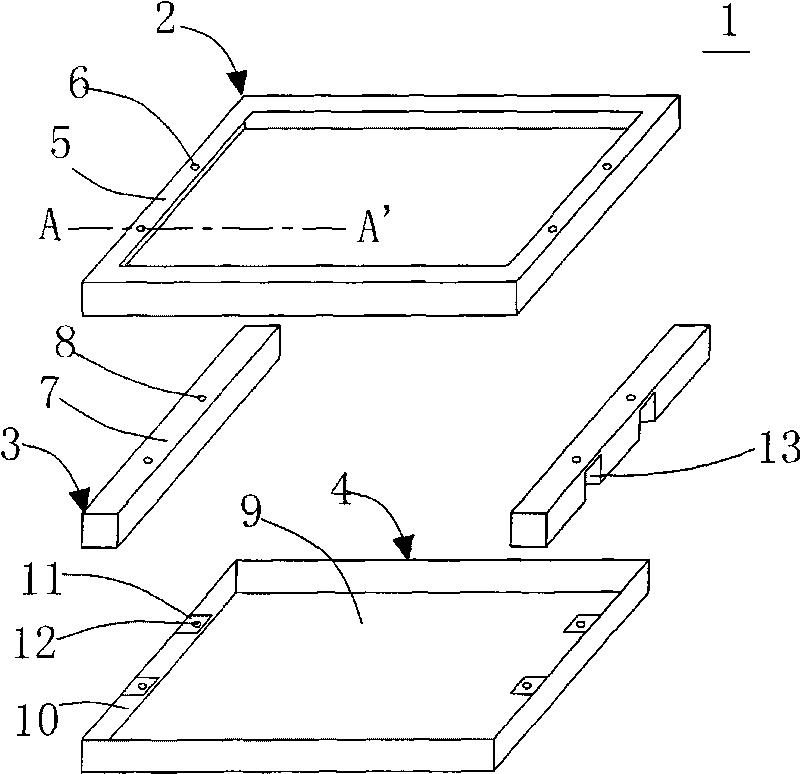
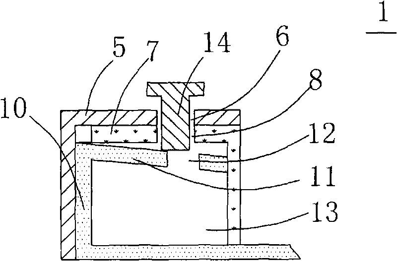
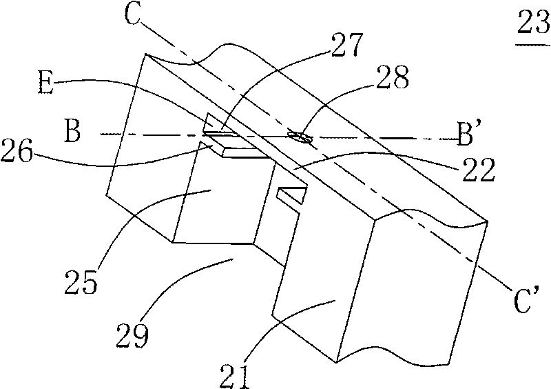
[0030] See image 3 , Figure 4 , Figure 5A as well as Figure 5B , image 3 Shown is a schematic view of a support seat according to a first embodiment of the present invention, Figure 4 Shown is a schematic view of a backplane according to a first embodiment of the present invention, Figure 5A shown as image 3 The support seat in the Figure 4 The schematic cross-sectional view along the BB' line after the back plate in the Figure 5B shown as image 3 The support seat in the Figure 4 Schematic cross-sectional view along the CC' line after the backplanes in . The backlight module 20 provided by the present invention includes a back plate 24 and a support base 23 . Since the structures of the light-emitting light source, the diffusing sheet, the prism sheet and the like disposed in the backlight module 20 are the same as those of the prior art, and are not the focus of the present invention, they will not be described here. The back plate 24 includes a bottom plate 19 , a side plate 16 extending upward from the edge of the bottom plate 19 and at least one lug 17 . The lugs 17 extend from the end of the side plate 16 away from the bottom plate 19 in a direction parallel to the bottom plate 19, and each lug 17 has a first through hole 18. In this embodiment, the shape of the lugs 17 is square, but In fact, it is not limited to this. The support base 23 is, for example, a lamp base for fixing the light source, and the setting of the lamp base 23 in the backlight module 20 is determined according to specific requirements. The support base 23 is placed on the bottom plate 19 , and the support base 23 includes at least one groove 29 and at least one support plate 26 . The cutout 29 extends from the side surface 21 of the support base 23 facing the side plate 16 to the inside of the support base 23 , and above the cutout 29 is a top plate 22 , which has a second through hole 28 corresponding to the first through hole 18 . The support plate 26 is disposed on the side wall 25 forming the groove 29 in parallel with the top plate 22 , and the support plate 26 , the top plate 22 and the side wall 25 form an accommodating area E and an opening 27 , and the lugs 17 are inserted into the accommodating area from the opening 27 . Inside E, the support base 23 and the back plate 24 are fixed by the fixing member 14 ′ in combination with the first through hole 18 and the second through hole 28 . The fixing member 14' is, for example, a screw, a bolt or a stud, or other fasteners that can be locked in combination with the through hole.
[0031] See Image 6 , Image 6 Shown is a schematic view of a backplane according to a second embodiment of the present invention. The structure of the back plate 34 in this embodiment is similar to that of the back plate 24 in the first embodiment, except that the structure of the lugs 37 of the back plate 34 is different, and the lugs 37 include the first part 71 and the first part 71 The second portion 72 is protruded from the edge, and the first portion 71 is connected to the side plate 16 and the second portion 72 . The first part 71 and the second part 72 are, for example, integrally formed with the back plate 34 . For example, the first through hole 18 on the lug 37 can be located at the first part 71, or the second part 72, or at the junction of the first part 71 and the second part 72. The setting of the first through hole 18 only needs to meet the The second through hole can be matched and locked. In this embodiment, it is taken as an example that the first through hole 18 is disposed on the second portion 72 .
[0032] Corresponding to the back plate 34 , the structure of the support seat 43 can also be changed accordingly. For details, please refer to Figure 7 , Figure 7 Shown is a schematic view of a support seat according to a second embodiment of the present invention. The structure of the support seat 43 in this embodiment is similar to the structure of the support seat 23 in the first embodiment, the difference is that the support plate 36 of the support seat 43 may be composed of, for example, a plurality of parts, which are separated from each other and used to support the convex The surrounding area of the ear 37 . That is, these parts can respectively correspond to and support two instances of the second part 72 and the first part 71 of the lug 37 , etc. The structure of the support plate 36 can be set according to the shape of the lug 37 .
[0033] In addition, in this embodiment, the support base 43 further includes a reinforcing block 46 , and the reinforcing block 46 connects the support plate 36 and the side wall 45 for reinforcing the support plate 36 . Since the support plate 36 is composed of a plurality of parts, in order to achieve a good reinforcement effect, a reinforcement block 46 can be provided corresponding to each part. In this embodiment, the reinforcing block 46 is located below the support plate 36 , but it is not limited to this.
[0034] See Figure 8A , Figure 8A Shown is a schematic view of a backplane according to a third embodiment of the present invention. The structure of the back plate 44 in this embodiment is similar to that of the back plate 24 in the first embodiment. Extend along the body of the lug 47 toward the side plate 16 . Corresponding to the back plate 44, for example, the structure of the support base 33 can also be modified accordingly. For details, please refer to Figure 9 , Figure 9 Shown is a schematic view of a support seat according to a third embodiment of the present invention. The structure of the support seat 33 in this embodiment is similar to that of the support seat 23 in the first embodiment, the difference is that the support plate 26 of the support seat 33 is further provided with a protruding column 38 , which is different from the lug 47 of the back plate 44 . Corresponding to the notch 73 provided above, when the lug 47 is inserted into the accommodating space E from the opening 27 , the protruding post 38 enters the notch 73 from the edge of the lug 47 and is positioned in combination with the notch 73 . On the one hand, the cooperation of the notch 73 and the protruding post 38 can play a role of positioning, and on the other hand, the cooperation of the two can also play a guiding role, which facilitates the insertion of the lug 47 into the accommodating space E. In this embodiment, notches 73 are provided on both sides of the first through hole 18 of the lug 47 , and two protruding posts 38 are also provided on the corresponding support plate 26 . But in fact, the design of the notch and the convex column can be determined according to the actual situation. In addition, the notches 73 can also be arranged on the support plate 26 as required, and the protruding columns 38 can be arranged on the lugs 47 correspondingly, which can also play the role of positioning and guiding.
[0035] See Figure 8B , Figure 8B Shown is a schematic view of a backplane according to a fourth embodiment of the present invention. The structure of the back plate 54 in this embodiment is similar to that of the back plate 34 in the second embodiment. The lug 57 of the back plate 54 includes a first part 77 and a second part 75 , and the difference lies in the first part of the lug 57 . A notch 76 is also provided, wherein the notch 76 extends from the edge of the first part 77 along the body of the first part 77 toward the side plate 16 . The notches 76 are arranged corresponding to the protruding posts 38 on the support base 33 . When the protruding lugs 57 are inserted into the accommodating space E from the openings 27 , the protruding posts 38 enter the notches 76 from the edges of the lugs 57 and combine with the notches 76 for positioning. On the one hand, the cooperation of the notch 76 and the protruding post 38 can play a positioning role, and on the other hand, the cooperation of the two can also play a guiding role, which facilitates the insertion of the lug 57 into the accommodating space E. Likewise, the design of the notch and the convex column can be determined according to the actual situation.
[0036] See Figure 10 , Figure 10 Shown is a schematic cross-sectional view of the assembled display device according to the present invention. The present invention also provides a display device 30 . The display device 30 includes a display panel, the above-mentioned backlight module 20 and a frame body 51 . The display panel is placed between the frame body 51 and the backlight module 20. The frame body 51 has a top surface 52 and a third through hole 58 on the top surface 52. The frame body 51 is, for example, a front iron frame, and the top surface 52 is hollow. structure, such as figure 1 shown in. The positioning member 60 passes through the third through hole 58 , the second through hole 28 and the first through hole 18 to fix the frame body 51 and the backlight module 20 . The fixing member 60 is, for example, a screw, a bolt or a stud, or other fasteners that can be used for fixing in combination with the through hole. Since the structure of the backlight module 20 is as described above, it will not be repeated here.
[0037] Compared with the prior art, the lugs of the back plate of the present invention are arranged in the accommodating area of the support seat, and the support plate provides a strong support function in structure, so when the screw is locked, it is not easy to be displaced due to external force. , and the through hole of the lamp holder and the locking of the frame body are not prone to dislocation, so it is beneficial to assembly, improve product yield, and reduce material scrap and heavy work.
[0038] It is hoped that the features and spirit of the present invention can be described more clearly by the detailed description of the preferred embodiments above, rather than limiting the protection scope of the present invention by the preferred embodiments disclosed above. On the contrary, the intention is to cover various modifications and equivalent arrangements within the scope of the claims to which the present invention seeks to apply. Therefore, the scope of protection of the claims to which the present invention applies should be construed in the broadest sense in accordance with the foregoing description so as to encompass all possible changes and equivalent arrangements.