
Coil forming method and forming mould for electromagnetic metering equipment

A metering equipment and coil forming technology, applied in coils, coil manufacturing, circuits, etc., can solve problems such as difficulty in ensuring coil dimensional accuracy, large coil magnetic flux leakage, and irregular arrangement, and achieve easy control of processing technology and discrete magnetic flux The effect of reducing and neatly aligning the coils

Inactive Publication Date: 2010-06-30
CHONGQING CHUANYI AUTOMATION +1
View PDF0 Cites 5 Cited by
  • Summary
  • Abstract
  • Description
  • Claims
  • Application Information

AI Technical Summary

Problems solved by technology

At present, coil manufacturers mostly use manual molding for the coil shape. This method is difficult to ensure the dimensional accuracy of the coils, and the coils are not dense and arranged irregularly.
In the process of use, the magnetic flux leakage of the coil is large, and the generated magnetic flux is highly discrete, which directly leads to inaccurate measurement results of the electromagnetic measuring equipment.

Method used

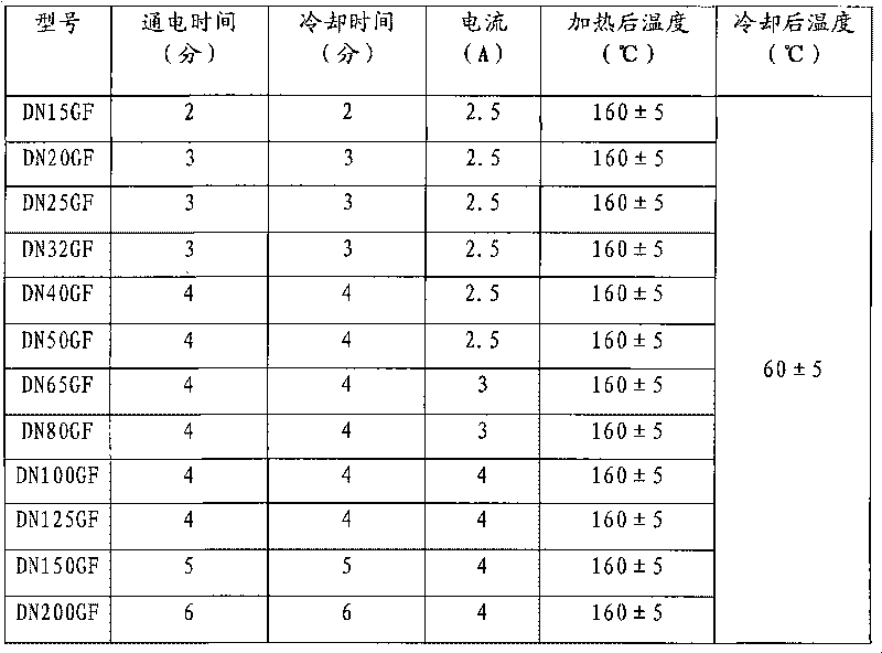

Image

  • Coil forming method and forming mould for electromagnetic metering equipment
  • Coil forming method and forming mould for electromagnetic metering equipment
  • Coil forming method and forming mould for electromagnetic metering equipment

Examples


Embodiment Construction

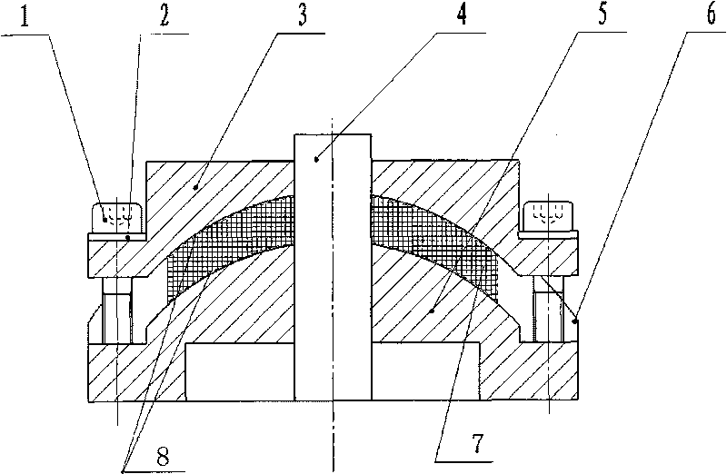
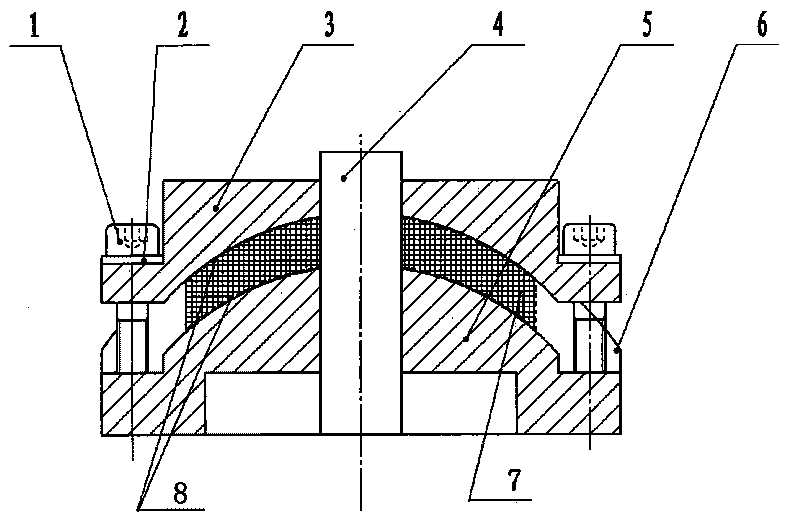
[0016] see figure 1 , a forming mold used for coil forming of electromagnetic metering equipment, the upper mold 3 is a concave mold with an upwardly concave cavity, and the lower mold 5 is a convex mold arc with an upwardly protruding cavity, and the radian of the cavity is the same as that of the end face of the coil mold. The bottom surface of the lower mold cavity is provided with a plane extending from the lower two ends, and a stop block 6 fixed with bolts on the plane, wherein the height of the stop block is equal to the thickness of the coil, is used to limit the position of the coil installed in the mould. The mold and the lower mold are fixed by screws 1, and the upper and lower molds are fixed and compressed. Liner 7 and pass patrix and counterdie and its gap cooperation.

[0017] When forming coils for electromagnetic metering equipment, first install the winding die on the automatic winding machine and fix it securely. Adjust the parameters of the winding machi...


PUM


Abstract

The invention relates to a coil forming method and a forming mould for electromagnetic metering equipment. The method comprises the following steps of: (1) mounting a winding former on an automatic winding machine and fixing; (2) winding by the winding machine to obtain a well-wound coil and winding the surface of the coil by using an insulating tape; (3) opening the forming mould and placing insulating layers in the upper mould and the lower mould; putting the coil in the lower mould and closing the mould; pressing the coil by using the upper mould and setting the current intensity of a voltage regulator in a heating mould; heating the coil to 155-165 DEG C and keeping the temperature for 2-6 minutes; and (4) after the coil is cooled to 55-65 DEG C, taking out the coil to obtain a coil for the electromagnetic metering equipment. The invention can guarantee the precision of the coil, has neat and compact coil array, reduces flux leakage in a use process, reduces the magnetic flow discreteness and is suitable for mass industrial production of enterprises.

Description

technical field [0001] The invention belongs to a coil forming method and device, in particular to a coil forming method and a forming mold for electromagnetic metering equipment. Background technique [0002] The coil used for electromagnetic measuring equipment has an arc-shaped end surface with an arc surface. Due to the high precision level of the electromagnetic metering device, the higher the precision level, the higher the requirements for the electrical performance and mechanical size of the coil. Usually the preparation process of the coil is to wind the coil on the wire winding mold first, and then shape the coil after the wire has been wound. At present, coil manufacturers mostly use manual molding for the shape of the coils. This method is difficult to ensure the dimensional accuracy of the coils, and the coils are not dense and arranged irregularly. In the process of use, the magnetic flux leakage of the coil is large, and the generated magnetic flux is highly...

Claims


Application Information

Patent Timeline
Patent Type & Authority Applications(China)
IPC IPC(8): H01F41/04H01F41/06H01F5/00
Inventor 张喜陈德平
Owner CHONGQING CHUANYI AUTOMATION
Learn More