
Magnetic coupling

A technology of magnetic couplers and permanent magnets, which is applied in the direction of electrical components, generators/motors, etc., and can solve problems such as failure and shedding, distortion of magnetic material arrangement, and unsuitable precision requirements.

Active Publication Date: 2012-07-11
INST OF MAGNETIC DEVICES GANSU ACAD OF SCI
View PDF0 Cites 0 Cited by
  • Summary
  • Abstract
  • Description
  • Claims
  • Application Information

AI Technical Summary

Problems solved by technology

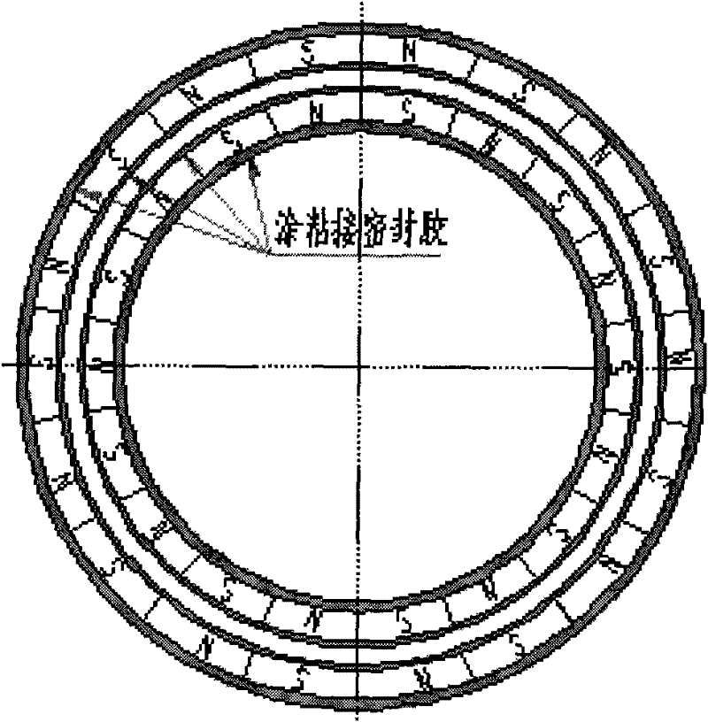
However, this fixing method is not suitable for some special applications. For example, in a nuclear reaction system, the organic adhesive used to fix the permanent magnet will fail and fall off due to factors such as radiation and high temperature, and the magnetic material will be distorted under the action of magnetic force. Unable to realize the function of transmitting torque
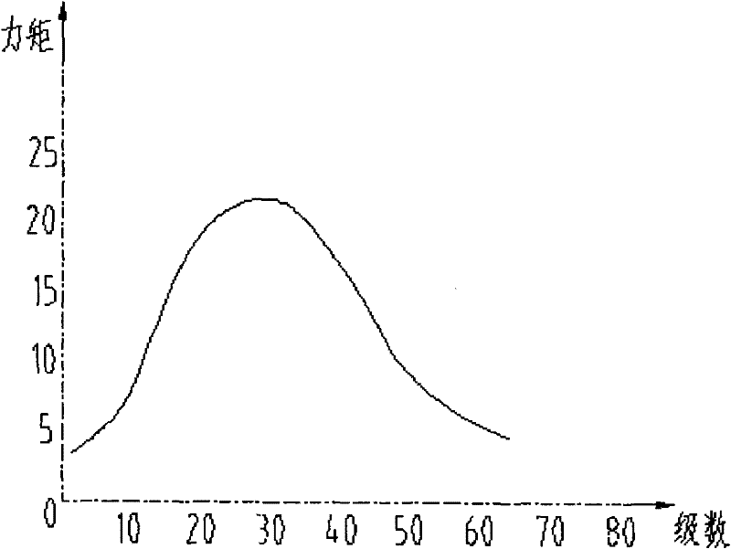
[0003] The second deficiency of the existing magnetic coupler is that when a large torque is transmitted, the inner and outer rotors will have a large lag angle. According to the actual test, the lag angle of the existing magnetic coupler when the torque is 50N.m is 9 degrees, such a large lag angle is not suitable for transmission with high precision requirements

Method used


Image

  • Magnetic coupling
  • Magnetic coupling
  • Magnetic coupling

Examples


Embodiment Construction

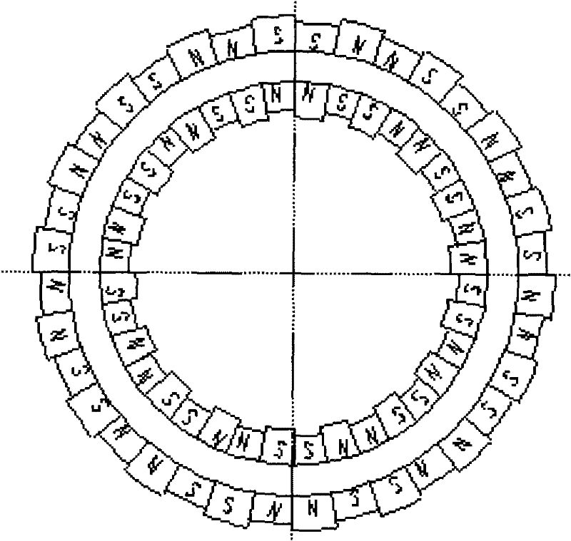
[0011] attached figure 2 For the concrete structure of an embodiment of the present invention, by figure 2 It can be seen that the N-S poles of the permanent magnets of the present invention are arranged along the axial direction of the rotor, but the outer circle of the inner rotor and the inner circle of the outer rotor of the present invention are respectively fixed with permanent magnets in a mosaic manner. In a specific implementation, the structure for the permanent magnet is processed at the inner and outer rotors by a wire cutting machine tool. In order to enable the permanent magnets to be inlaid well on the inner and outer rotors, the permanent magnets can be processed into wedge-shaped shapes with slightly different sizes according to the inlay combination.

[0012] The relevant experiments of the present invention show that when the magnets are embedded, every two permanent magnets with the same polarity are grouped into one group, and the opposite polarities of...


PUM


Abstract

The invention relates to a magnetic transmission device which can transfer larger torque and have smaller rotational hysteretic angle at the same time. Permanent magnet bodies are respectively fixed on the outer circle of an inner rotor and the inner circle of an outer rotor through embedded structure, the N-S poles of each permanent magnet body are arranged axially along the rotors, the permanent magnet bodies fixed on the rotors or a stator through embedded structure are arranged in the way that each two permanent magnet bodies with the same polarity are arranged with polarity opposite to the polarity of adjacent two permanent magnet bodies to form the structure such as NNSSNNSS....

Description

technical field [0001] The invention relates to a magnetic transmission device, which is commonly called a magnetic coupling. The magnetic coupler of the present invention consists of permanent magnets fixed on the outer circle of the inner rotor and permanent magnets fixed on the inner circle of the outer rotor, and shaft couplings respectively arranged on the shaft of the inner rotor and outside the outer rotor, and bearings constitute. Background technique [0002] The magnetic coupling is a magnetic transmission device that uses the magnetic force generated by the permanent magnet material or the electromagnet to realize the non-contact transmission of force or torque (power). The magnetic material in the existing magnetic transmission device is arranged adjacently by two magnets with opposite polarities. figure 1 As shown, large magnetic blocks are arranged on the inner and outer rotors, and then glued and fixed with adhesive. However, this fixing method is not suita...

Claims


Application Information

Patent Timeline
IPC IPC(8): H02N11/00
Inventor 赵克中闫雪兰
Owner INST OF MAGNETIC DEVICES GANSU ACAD OF SCI
Learn More