Bean milk machine with hand-mill stirrer

The technology of agitator and soymilk maker is applied in the directions of milk substitutes, beverage preparation devices, household appliances, etc., which can solve the problems of inconvenient cleaning of appliances, potential safety hazards, inconvenient cleaning of the kettle body, etc., so as to reduce cleaning difficulty, low cost, The effect of combined structure safety

Inactive Publication Date: 2010-07-07
周伟全
View PDF1 Cites 11 Cited by
  • Summary
  • Abstract
  • Description
  • Claims
  • Application Information

AI Technical Summary

Problems solved by technology

[0002] Existing soymilk machines use electric stirring and electric heating, and the beans need to be stirred before heating, because it contains motor parts and stirring knives, it is very inconvenient to clean the appliance after the production is completed, and the manufacturing cost is high. Published by the Patent Office: the patent number is 200420071297.2, and the name of the utility model is: multifunctional automatic soybean milk machine. The bottom of the cup body is provided with the upper connection head of the motor and the upper connection box of the power supply. The knife assembly driven by the motor, the cylindrical filter screen and the electric heating tube are arranged in the cup body; the faucet is arranged outside the bottom of the cup body; The motor and its lower connector, the lower connection box of the power supply and the control circuit board; the upper and lower parts are connected to the power source through the upper and lower connectors of the motor, and the upper and lower connection boxes of the power supply are plugged and connected to the heating source
However, there are still shortcomings: 1. The electric stirring device is used, which makes the product manufacturing cost high and not energy-saving; 2. The sealing ring is used for a period of time, and it is easy to leak to the motor, and it is easy to burn the motor, which has potential safety hazards; 3. , Using a mixing knife structure, it is inconvenient to clean the pot body

Method used


Image

  • Bean milk machine with hand-mill stirrer
  • Bean milk machine with hand-mill stirrer
  • Bean milk machine with hand-mill stirrer

Examples


Embodiment Construction

[0012] Hereinafter, the present invention will be further explained in detail with reference to the drawings.

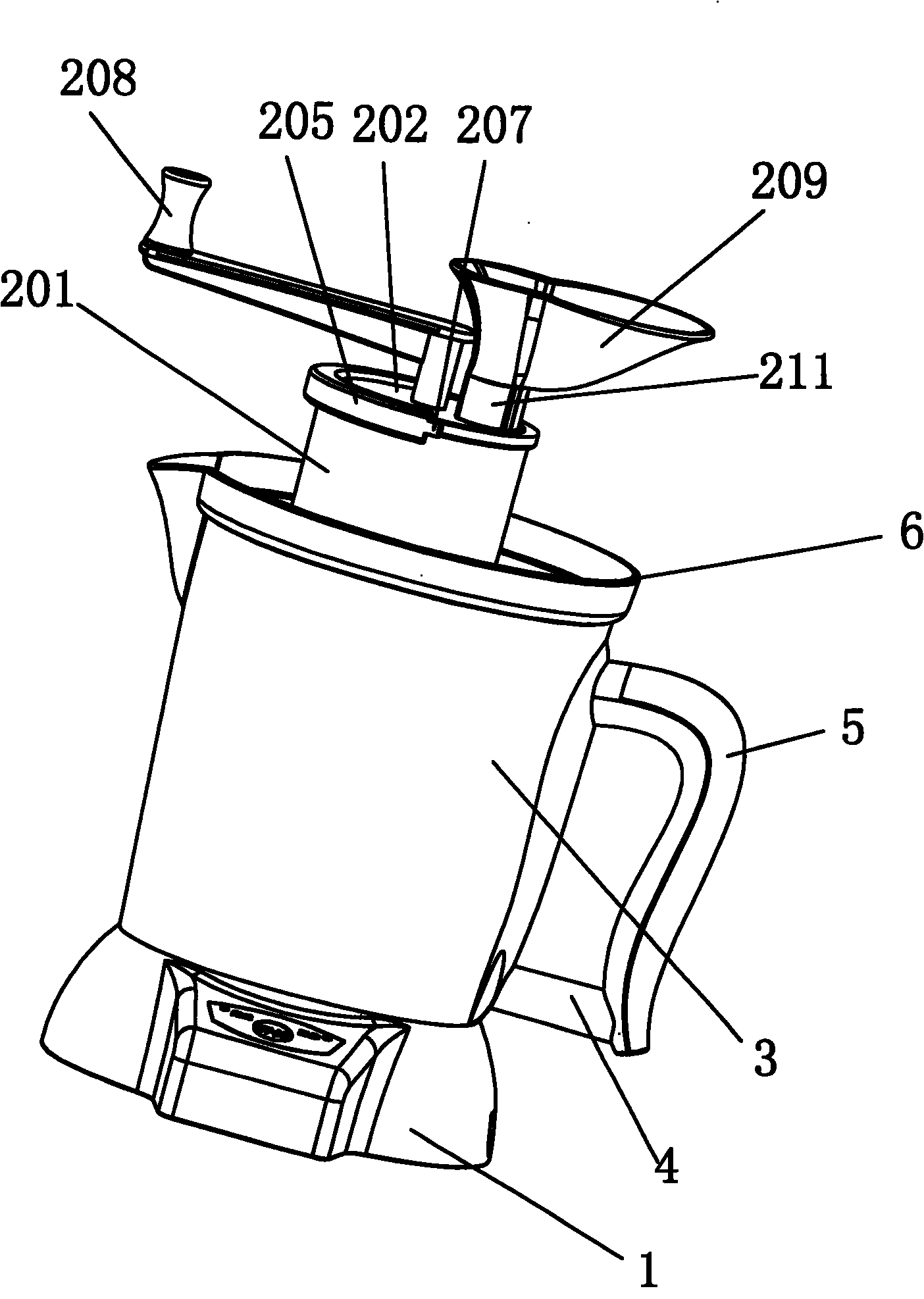
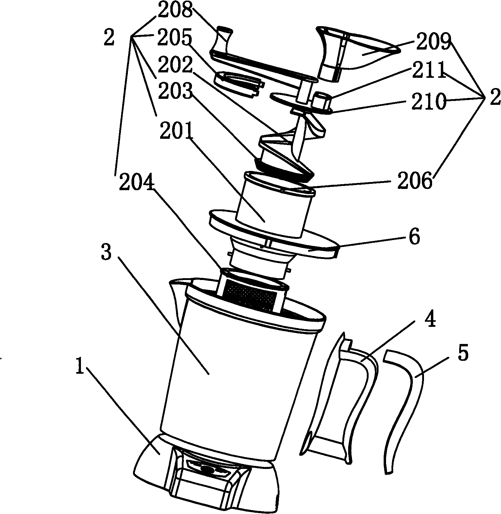
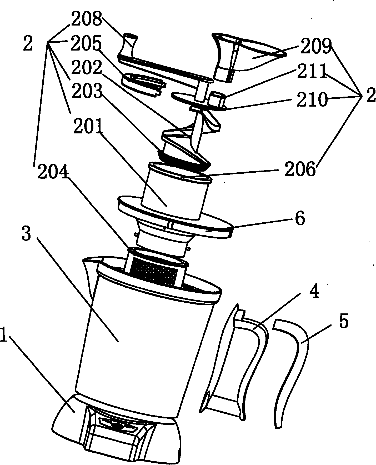
[0013] As shown in the figure, it includes a main body 3, a base 1 and a feeding rack 6. The main body 3 is connected with a handle 4, the base 1 is provided with an electric heating element, and the feeding rack 6 is provided with a stirring device 2 which includes There is a cavity in the grinding cylinder 201, and there is a worm 202 in the cavity. One end of the worm 202 has a spiral grinding pattern 203, and the other end is provided with a rocker 208. The bottom of the grinding cylinder 201 is also provided with a spiral grinding pattern 203. Grinding, the bottom and middle of the grinding cylinder 201 are provided with slurry outlets.

[0014] A filter cover 204 is wrapped around the slurry outlet of the mill cylinder 201.

[0015] The outer circle limiting convex part 206 of the upper part of the grinding cylinder 201, and a locking member 205 locks the worm 202 in...


PUM


Abstract

The invention relates to the technical field of bean milk machines, in particular to a bean milk machine with a hand-mill stirrer. The bean milk machine with the hand-mill stirrer comprises a main body, a base and a charging frame, wherein the main body is connected with a handle, the base is provided with an electrical heating element, and a stirring device is arranged on the charging frame and comprises a milling barrel in which a cavity is arranged; a worm is arranged in the cavity, the circumferential surface of one end of the worm is provided with spiral milling grains, and the other end is provided with a rocker arm; and a part on the bottom of the milling barrel, which corresponds to the spiral milling grains, is also provided with milling grains, and the bottom and the middle of the milling grains on the bottom of the milling barrel are provided with bean milk outlets. The bean milk machine with the hand-mill stirrer has the advantages that the structure has relatively low cost and saves energy by adopting the mechanical stirring device, thereby enduing the product with high cost performance; the technology of the traditional heating mode is mature and is relatively low-cost, thereby being applicable to general consumer groups; and the structure has simple combination mode, less components and integral design of most of components, such as the stirring device, and the bean milk machine can be cleaned by a user through only a few of steps.

Description

Technical field [0001] The invention relates to the technical field of soymilk machines, in particular to a soymilk machine with a hand grinder. Background technique [0002] The existing soybean milk machine is heated by electric stirring and electric heating. It is necessary to stir the beans before heating. Because it contains motor parts and stirring knives, it is very inconvenient to clean the utensils after the production is completed, and the manufacturing cost is high. Published by the Patent Office: The patent number is 200420071297.2, and the utility model name is: Multifunctional automatic soymilk machine. The structure is: including a body and a control circuit, consisting of two parts that can be separated from the upper part and the lower part; the upper part is the cup body and the cup The bottom of the body is equipped with a motor connection head and a power supply connection box. The cup body is equipped with a motor-driven knife assembly, a cylindrical filter s...

Claims


Application Information

Patent Timeline
Patent Type & Authority Applications(China)
IPC IPC(8): A23L1/20A23C11/10A47J31/44A23L11/60
Inventor 周伟全
Owner 周伟全
Why Eureka
Try Eureka