Metal tube flaring molding machine

A forming machine and metal tube technology, applied in the field of metal tube flaring forming machines, can solve problems such as low production efficiency, high energy consumption, and welding residues of pipe fittings, and achieve high production efficiency, low noise, and less pollution.

Inactive Publication Date: 2010-07-07
丹佛斯动力系统(宁波)有限公司
View PDF1 Cites 32 Cited by
  • Summary
  • Abstract
  • Description
  • Claims
  • Application Information

AI Technical Summary

Problems solved by technology

[0002] The traditional pipeline connection methods mainly include direct welding connection and flange welding connection. Both of these two connection methods require welding operations, and the welding methods have some disadvantages: such as the need for skilled welders; There are certain welding residues inside the connected pipe fittings, etc.
However, the above-mentioned technology has the following disadvantages: 1. Noise and environmental pollution: the hydraulic press needs a motor-driven oil pump to drive the oil cylinder and the mechanical pressure of the mold under the control of the valve group to complete the stamping action; although the portable press does not need a motor drive, it needs hydraulic oil. And the hydraulic cylinder, the user needs to shake the lever constantly to make the punch complete the punching action
Both of these forms will lead to increased environmental pollution such as high noise or oil leakage
2. Low production efficiency and high labor intensity for operators
3. Electric energy, mechanical-hydraulic conversion transmission system has high loss, continuous energy consumption in non-working state, and large energy consumption

Method used


Image

  • Metal tube flaring molding machine
  • Metal tube flaring molding machine

Examples


Embodiment Construction

[0016] The present invention will be further described in detail below in conjunction with the accompanying drawings and embodiments.

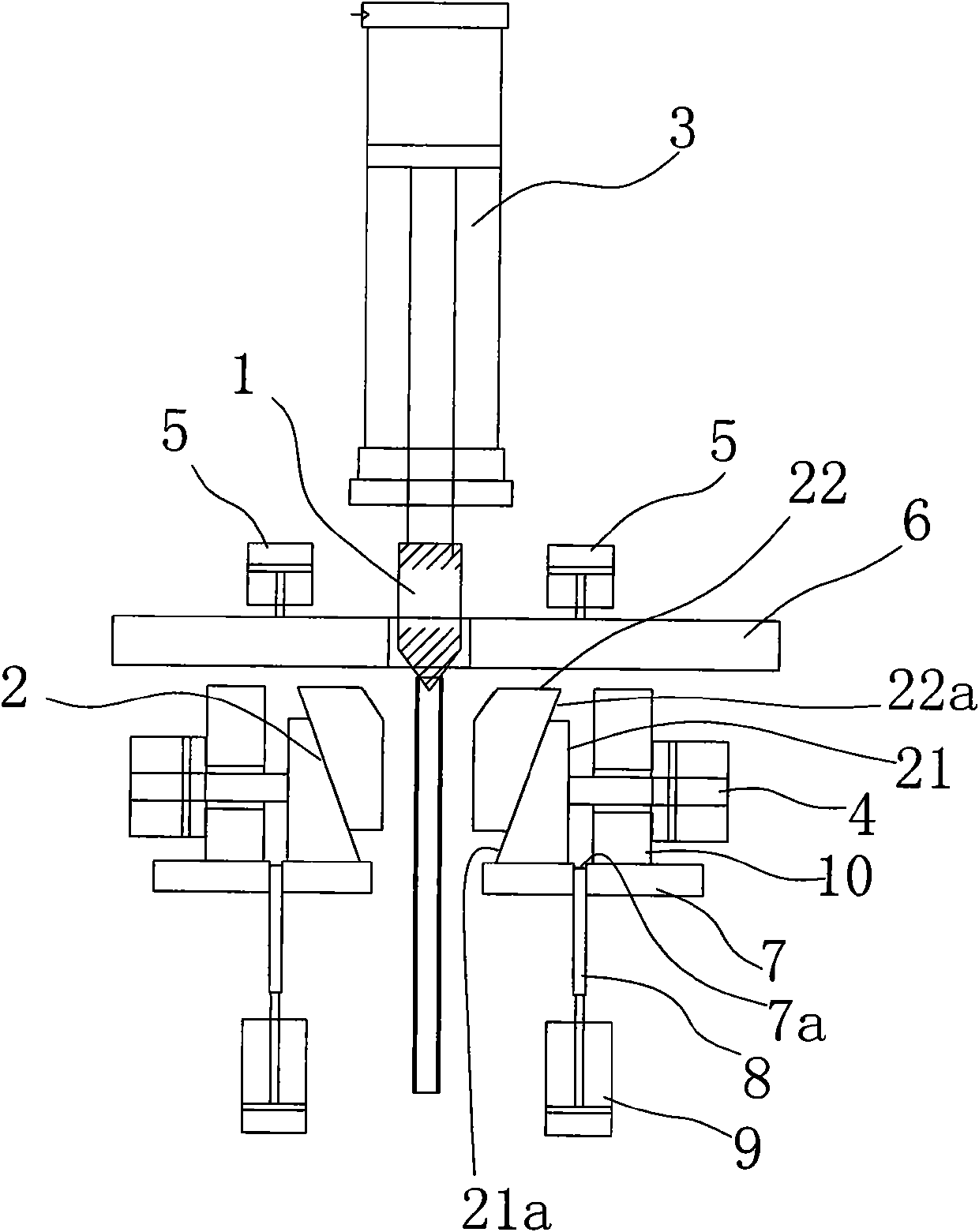
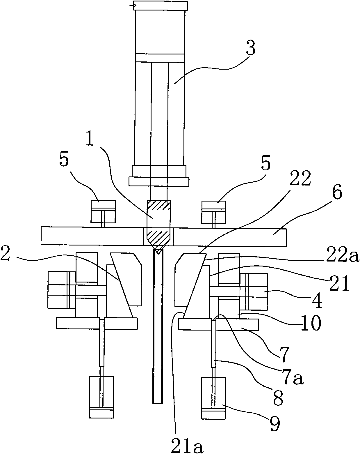
[0017] In the embodiment shown in the figure, the reference numerals explain: punch 1, clamping die assembly 2, inclined block 21, first inclined surface 21a, clamping member 22, second inclined surface 22a, gas-hydraulic booster cylinder 3, clamping Cylinder 4, compression cylinder 5, push plate 6, fixed plate 7, slide block groove 7a, slide block 8, slide block cylinder 9, baffle plate 10.

[0018] As shown in the figure, a metal tube flaring forming machine includes a frame, a punch 1 arranged on the frame, and two clamping die assemblies 2 that cooperate with the punch 1 The clamping die, the rear end of the punch 1 is connected with a gas-liquid booster cylinder 3, and the two clamping die components 2 are connected with a clamping cylinder 4.

[0019] Wherein, the clamping mold assembly 2 of the clamping cylinder 4 includes an inclined ...


PUM


Abstract

The invention relates to a metal tube flaring molding machine, comprising a rack, a punch and a clamping mould, wherein the punch is arranged on the rack, the clamping mould which is composed of two interworking clamping mould components is matched with the punch, the rear end of the punch is connected with a pneumohydraulic pressure-cylinder, and at least one of the two clamping mould components is connected with a clamping cylinder. Compared with prior art, the invention has the advantages of easy operation, low labor intensity. In addition, because all mechanical operations are driven by a relevant cylinder, needless of motors or other power sources, and a muffler is used to air source exhaust for noise reduction, the noise during operation is low; no oil or chemical pollution generates due to air source served as power source; no compressed air is consumed when the machine is standby, so the energy consumption is low; and the frequency of two flaring actions per minute under the condition of good quality is higher than common oil presses and rotation type machines, so the production efficiency is high.

Description

technical field [0001] The invention relates to a metal tube flaring forming machine. Background technique [0002] The traditional pipeline connection methods mainly include direct welding connection and flange welding connection. Both of these two connection methods require welding operations, and the welding methods have some disadvantages: such as the need for skilled welders; The connected pipe fittings have certain welding residues inside. For this reason, a non-welded pipeline connection method has emerged in recent years. This technology connects the flared pipe fittings through flanges and seals without welding. Compared with the original welding connection, the non-welded connection technology has the following advantages: simple operation , reducing the technical requirements for workers; no stress and leakage; no need for radiographic inspection; it can ensure the cleanliness inside the pipeline. The key of non-welded connection technology lies in the flaring p...

Claims


Application Information

Patent Timeline
Patent Type & Authority Applications(China)
IPC IPC(8): B21D41/02
Inventor 周阳春潘峰
Owner 丹佛斯动力系统(宁波)有限公司
Why Eureka
Try Eureka